Yaskawa J50M Instructions User Manual
Page 34
2.9.7 EXACT STOP
G61, G64) (Cent’d)
Notes :
. In the Error Detect On mode, the program pro-
ceeds to the next block only after the number
of servo delay pulses is found to have decreas-
ed below a permissible limit following the com-
plete distribution of circular interpolation
command pulses.
In the G09 and G61. off modes, the program pro-
ceeds to the next block immediately after the
complete distribution of the pulses of ordinary
linear and circular interpolations, and there-
fore, because of the servo delay, tool pathes
are rounded at the corner. This mode is called
Detect
‘ode”
. For rapid traverse, the Error Detect On and
Off modes are controlled only by GOO and
G 0 6 ,
and not by the above G codes.
2.9.8 TOOL OFFSET VALUE DESIGNATION (G1O)
With a G1O command, correction of tool offset
values and work coordinate system can be made
as follows.
(1) Designation of tool offset value ( G1O)
Normally, tool offset values are written in by
MDI .
On the other hand, with a program G1O
.
.
; , (where P = tool offset number
and R = tool offset value) , any programmed
offset values can be replaced by a designated
value.
When G1O is commanded in the G90 mode, R is
stored as it is.
When G1O is commanded in the G91
added in the previous tool offset value.
(’2)
coordinate
(a) Corresponding to G54 through G59,
work coordinate systems are set up
data in advance.
G 1 O
P m X . . . Y . . , Z . . . ( a . . . )
mode. R is
separate
as setting
(b) For the work coordinate system setting B
specification, change the setting of the work
coordinate system by
G 10
Pm Jn X . . .
Y.. . z.. .
(Jn specifies
to J5. The
meaning of
and
is the same as mentioned in
(a).)
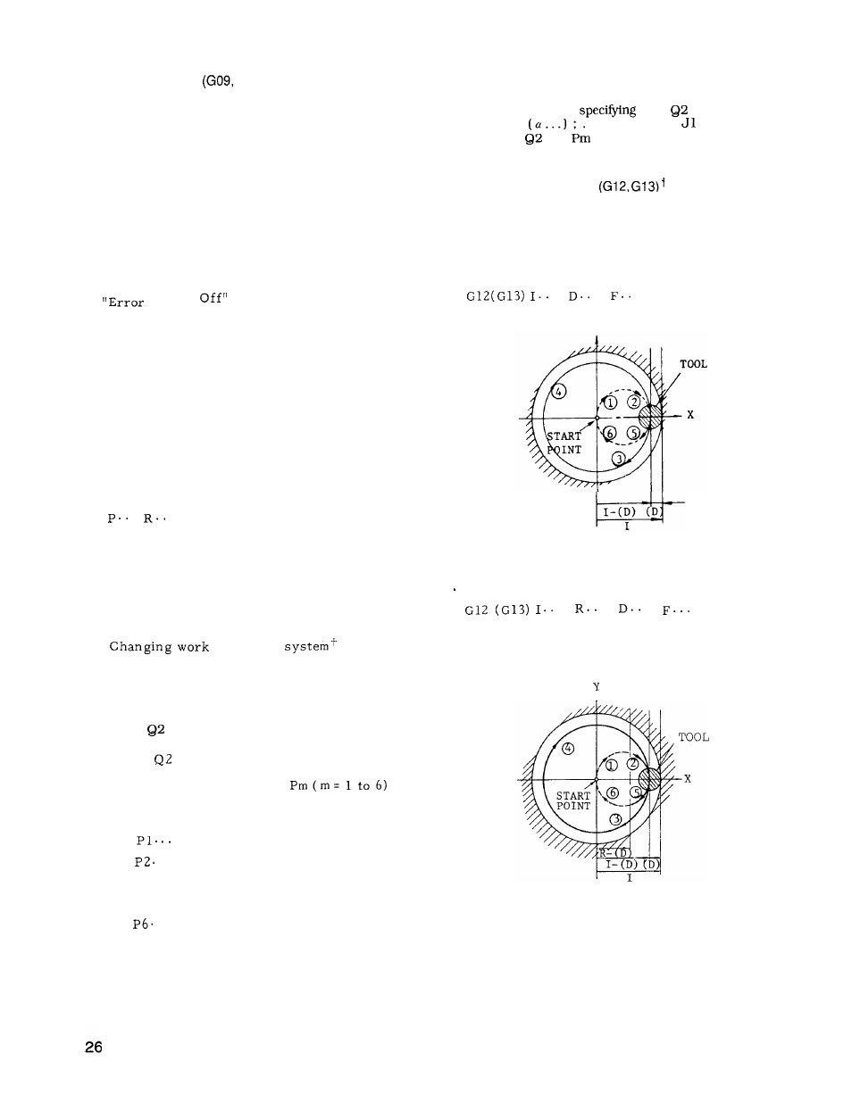
2.9.9 CIRCLE CUTTING
This is a canned cycle which includes a complete
series of movements for machining a circle in a
single block.
It includes the following functions.
. Format
.
.
. ;
Y
Fig. 2.19
Designation of rapid traverse section R
.
.
.
;
With this command , a circular bore is machined
as shown below.
Numerals following an address
character R specifies rapid traverse sections.
I
(where
is used to discriminate from tool
offset value designation and a means to set up
a work coordinate system.
corresponds to the work coordinate system m
to be set up. )
F o r
G 5 4
For
. . G55
Fig. 2.20
For
. .
G59 corresponds.
With the above command, data of any desired
work coordinate system can be changed.