Traverse and feed functions – Yaskawa J50M Instructions User Manual
Page 17
:
The machine may not function properly if
a move command over the maximum programmable
value is given The above maximum program-
mable values also
to distance command ad-
dresses I, J, K, R, Q
addition to move com-
mand addresses X , Y, Z ,
The accumulative value must not exceed the maxi-
mum accumulative values shown below .
Table 2.12 Maximum Cumulative values
Linear axis
R o t a r y
Metric input
99999.999 mm
99999.999 deg
Inch input
9999.9999 in.
99999.999 deg
Listed input values do not depend on metric/
inch output system.
2.4
TRAVERSE AND FEED FUNCTIONS
2.4.1 RAPID TRAVERSE RATE
2. 4.1.1 RAPID TRAVERSE RATE
The rapid traverse motion is used for the motion
for the Positioning
and for the motion for
the Manual Rapid Traverse (RAPID) . The trav-
erse rates differ among the axes since they are
dependent on the machine specification and are
determined by the machine tool builders. The
rapid traverse rates determined by the machine
are set by parameters in advance for individual
axes.
When the tool is moved in rapid traverse
in two or three axial directions simultaneously ,
motions in these axial directions are independent
of each other, and
end points are reached at
different times among these motions. Therefore,
motion paths are normally not straight.
For override rapid traverse rates , Fo, 25%, 50%
and 100% of the basic rapid traverse rates , are
available.
Fo is a constant feed rate set by a
parameter ( #6231) .
2. 4.1.2 SETTING RANGE OF RAPID TRAVERSE
R A T E
For each axis, rapid traverse rates can be set
at some suitable multiple of O. 001
(or deg /
min ) .
The maximum programmable rapid traverse rate is
30,000
However, respective machine tools
have their own optimum rapid traverse rates. Refer to
the manual provided by the machine tool builder.
2.4.2
FEEDRATE (F-FUNCTION)
With five digits following an address character F,
tool feedrates per minute (mm /rein) are program-
med.
Table 2.13 Programmable Range of Feedrate
Feedrate
(Feed/rein) range
Metric
Metric input
F50
F1.-F3OOOO.O mm/min
output
Inch input
F31
FO.1-F1181.1O in. /rein
Inch
Metric input
F50
output
Inch
F31
FO. 1-3000.00 in. /rein
The maximum feedrate is subject to the perform-
ance of the servo system and the machine system.
When the maximum feedrate set by the servo or
machine system is below the maximum program-
mable feedrate given above, the former is set by
a parameter ( #6228) , and whenever feedrates
the set maximum limit are commanded, the
feedrate is clamped at the set maximum value.
F commands for linear and circular interpolations
involving motions in simultaneously controlled
two axial directions specify feedrates in the direc-
tion tangential to the motion path.
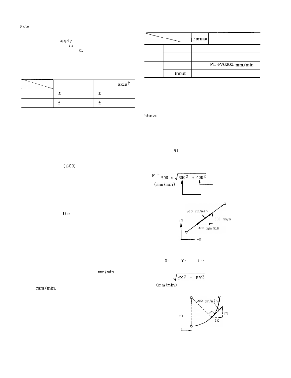
EXAMPLE G
(incremental)
GO1 X40.
Y30.
F500
With this command,
X component
Y component
500 nun/rein
, 300
400
Fig. 2.2
G03
. . .
. . .
. F200
With this command,
F = 200 =
CENTER
\
.,200
I
I
l
\ \
I
+x
in
The programmable range of feedrates is as follows.
Fig. 2.3
9