Yaskawa J50M Instructions User Manual
Page 19
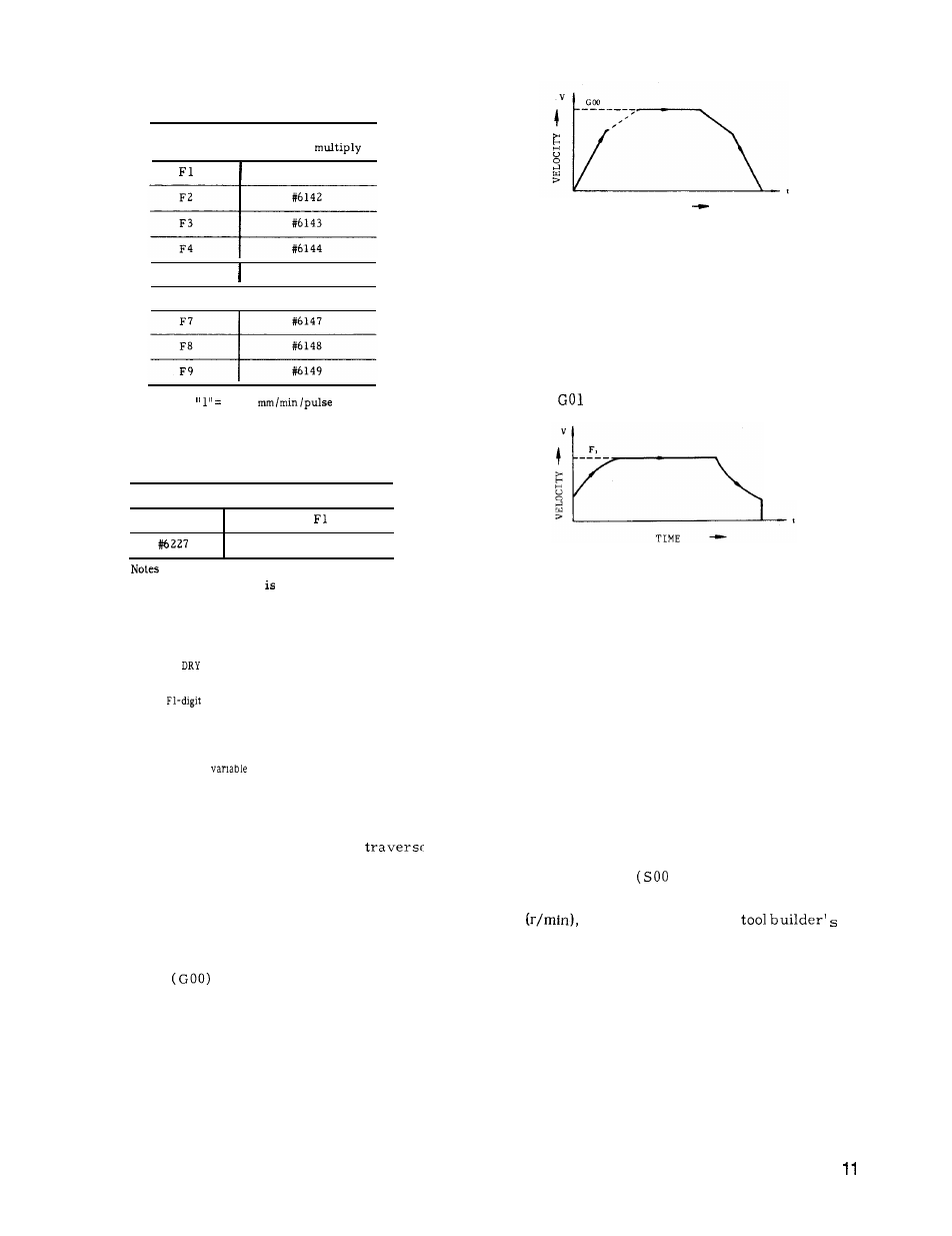
Table 2.15 (b) F Command and
Parameter No.
F
command
I
Parameter No. for
F1-digit
#6141
F5
#6145
F6
I
#6146
Setting O.
1
Table 2.15 (c) Parameter No. for
Maximum Feedrate
Parameter No. I
Meaning
#6226
Max speed of
to F4
Max speed of F5 to F9
:
a.
When this feature installed, the specifying
1 to 9 mm /rein by the usual
F
function is not al-
lowed.
Specifying
10 mm /rein or more is allowed
usually.
b. If FO is specified, error “ 030”’ will be caused.
c. When
RUN switch is on, the rate of dry
run is assumed.
d.
For
specification, the feedrate over-
ride feature is invalid.
e. The feedrate stored in memory is retained
after the power is turned off.
f.
For the
command of micro-program
F l-digit command is possible.
2.4.5
AUTOMATIC ACCELERATION AND DECELERATION
Acceleration and deceleration for rapid
and cutting feed are automatically performed.
2.4.5.1
A C C E L E R A T I O N A N D D E C E L E R A T I O N
OF RAPID TRAVERSE AND MANUAL FEED
In
the following operation , the pattern of auto-
matic acceleration and deceleration is linear .
. Positioning
. Manual rapid traverse (RAPID)
. Manual continuous feeding (JOG)
. Manual HANDLE feeding (HANDLE)
The 2-step linear acceleration/deceleration can be speci-
fied shown in Fig. 2.5.
TIME
Fig. 2.5
Rapid traverse rate and acceleration deceleration
constant of rapid traverse rate can be set by
parameter. (#6280 to #6301)
2.4.5.2
ACCELERATION /DECELERATION OF
FEEDRATE
Automatic acceleration and deceleration of feed
motion (
- G03) are in the exponential mode.
Fig. 2.6 Exponential acceleration
deceleration
Feedrate time constants and feedrate bias are
set by parameters. During tapping, another time
constants and bias other than for usual feedrate
can be set by parameters (#6406 -#6434) .
Note:
The automatic acceleration /deceleration param-
eters are set to the optimum values for the re-
spective machines.
Do not change the setting
unless this is required for special purposes.
2.5 SPINDLE-SPEED FUNCTION (S-FUNCTION)
2.5.1 S 2-DIGIT PROGRAMMING
The spindle speed is specified by two digits fol-
lowing the address S
to S99) .
For each S code and its corresponding spindle
speed
refer to the machine
manual.
When a move command and an S code are issued in the
same block, whether the S command is executed togeth-
er with the move command or after the completion of tool
move depends on the machine tool builder. Refer to the
machine tool builder’s manual.
S codes are modal, remaining effective, when
once commanded, until next S code is commanded.
If the spindle is stopped by M05 (spindle stop)
command, the S command in the control is kept.