Yaskawa J50M Instructions User Manual
Page 72
2.9.25
WORK COORDINATE SYSTEM SETTING C
(G52 TO G59)
t
(4)
Work coordinate system setting
Setting is performed in the same way as for work
coordinate system setting B.
Rotation is added to
move the work coordinate system.
(a) G54 Jn;
(n = 1, 2, to 5)
With this command, all later programs move on the
. .
work coordinate sYstern.
G54 to G59
modal commands.
(b) The G54; command and G54
are equivalent.
(c) Commanding numerals exceeding J6 causes alarm
(d) When J2 to J5 are commanded, the shift amount of
the 4th axis becomes O and returns to the basic coordi-
nate system.
(5) Returning to the basic coordinate system
(a) G52;
With this command, the currently selected work
coordinate system is canceled, to return to the
basic coordinate system.
(b) G52 is modal.
(6) Program example
G92 XO YO ZO:
G54;
.
.
.
.
G55;
.
.
.
.
G52;
.
.
.
.
Nothing changes under G92.
(G68 XO YO R
(value
of
Shifts the work coordinate system by G54,
and rotates the coordinate system for R,
centering the work coordinate system (O, O).
(G68 XO YO
R (value of #6527))
Shifts the work coordinate system by G54
and cancels the rotation, to create a new
coordinate system by the G55 work
coordinate system shift amount and rotary
angle.
Returns to the G92 coordinate system
G52.
The rotation is also canceled.
(
) shows what the program will be
when actually programmed.
(7)
move in the machine coordinate
b y
like
system
‘
As in the A-specification, the move on the machine
coordinate system can be temporarily commanded by
the G53 command.
G53 is a non-modal G code.
( E x a m p l e ) G 5 3
GOO
(a... ) ;
64
(8) Work coordinate system alteration by G1O
A s i s t h e w o r k c o o r d i n a t e s y s t e m A - a n d
specifications,
the work correction of the coordinate
system can be commanded from the program by the
G1O command.
(a) G1O Q2 Pm Jn
Z... a... R... ;
Command as above, to correct the specified work
coordinate system.
The combination of Pm and Jn specifies the
coordinate system to be corrected.
Select G54 to G59 by
= G44
to
P
6 = G59
Select
to J5 by
.
●
Example
P2 J3
. . . G55 J3
P4
. . . G57
(b) When J is omitted or when JO is specified, it is
regarded as
(c) When a wrong numeral is commanded for m or
o c c u r s .
(d) The 4th axis command is enabled when J2 to J5 are
commanded.
(This is added to the work coordinate system shift
specifications).
( e )
corrects the rotary angle,
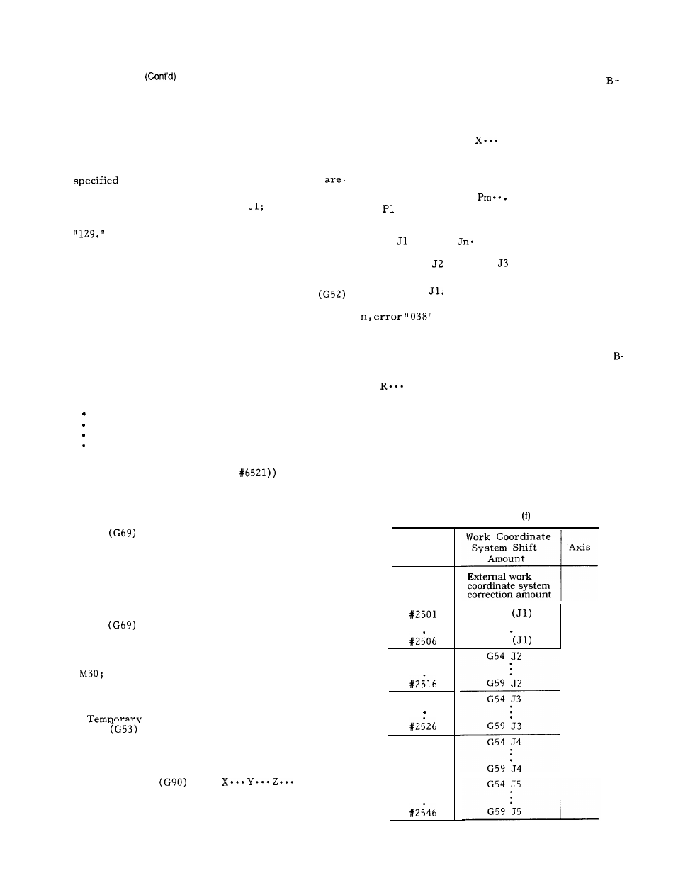
(9) Work coordinate system shift amount in the
macro program
(a) The following system variables are added to the
macro, by the addition of the work coordinate
system shift amount.
(b) The notes and how to use the system variables
are the same as the A- and B-specifications.
System
Variables
#2500
.
.
#2511
.
.
#2521
.
#2531
.
.
#2536
#2541
.
.
Table 2.26
Work Coordinate
System Shift
Axis
Amount
External work
coordinate system
correction amount
G54
.
.
G59
G54
.
.
.
G59
G54 J3
x
.
G59
G54 J4
.
G59