Yaskawa J50M Instructions User Manual
Page 31
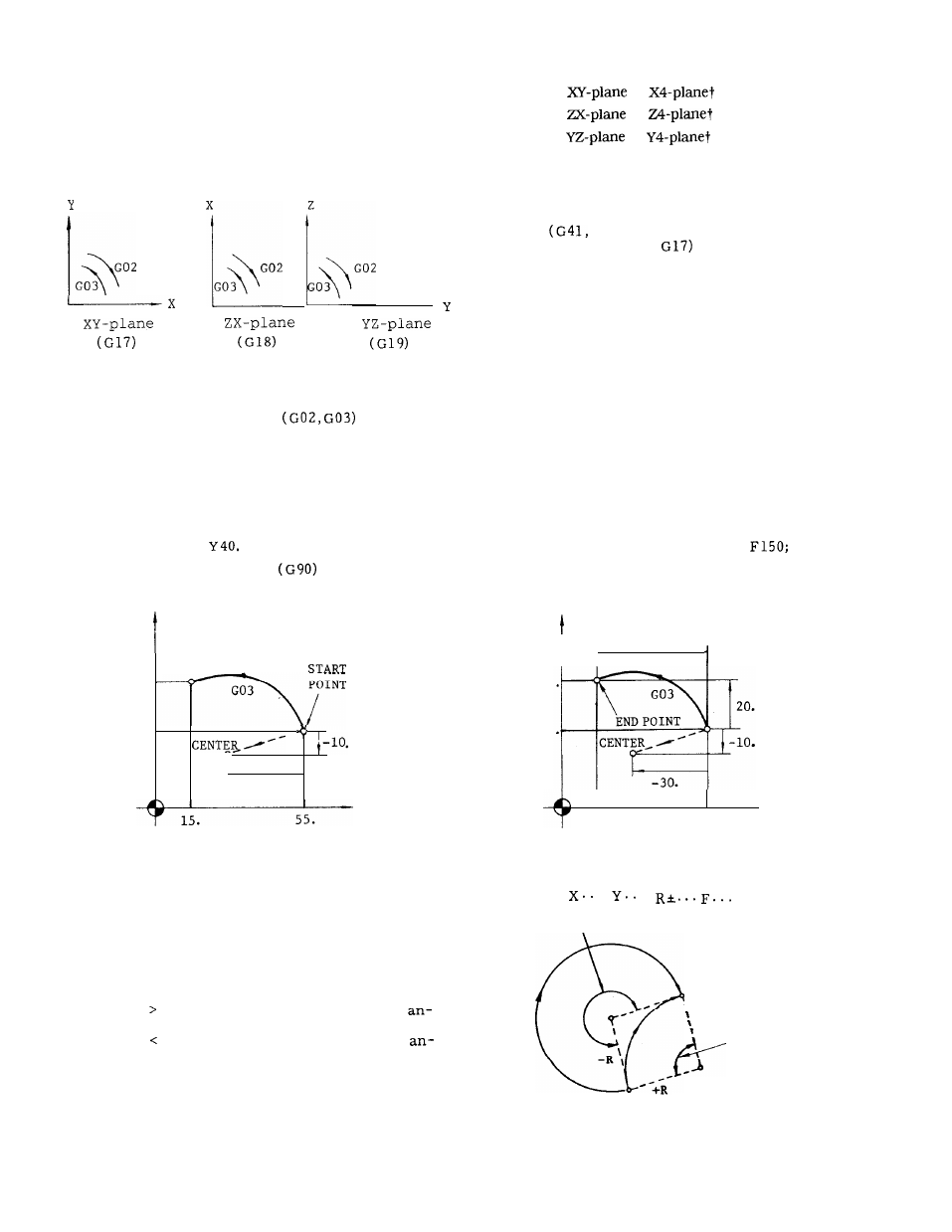
The moving direction of the tool along the circle
is as follows.
G02:
Clockwise
G03: Counter-clockwise
,
Fig. 2.13
When circular interpolation
is to be
programmed, usually, the plane of interpolation
should be specified in advance with G17, G18 or
G19.
EXAMPLE
G17 G90 G03 X15,
I-30. J-10. F150 ;
(a) Absolute command with
Y
END POINT
40.
20. ,
-
-30.
x
G17 :
or
G18 :
or
G 19:
or
(when the 4th axis is linear)
In addition to the plane of circular interpolation,
these G codes specify planes for tool radius com-
pensation
G42) .
If no selection is made to
the contrary, XY plane (
is selected auto-
matically immediately after the switching of the
power supply.
The end point of the circular arc may be specified
by G90 or G91 respectively in absolute or incre-
mental values.
However, the center of the circle
is always programmed in incremental values from
the start point, irrespective of G90 or G 91.
G17 G91 G03 X-40. Y20. 1-30. J-10.
(b) Incremental command
40
20
Y
I t-
-40.
I
x
15.
55.
Fig. 2.14
Instead of the coordinates 1, J, and K of the
G17 G02
.
.
;
center of the circle, the radius can be directly
specified with an R command.
This is called
180° OR OVER
circular interpolation with radius R designation
mode.
In this case,
END POINT
when R 0, a circular arc with the center
\
gle less than 180°, and
when R 0, a circular arc with the center
\
gle larger than 180° are specified.
180” OR BELOW
-R
START POINT
Fig. 2.15
23