Yaskawa J50M Instructions User Manual
Page 100
2.9.34
SETTING OF LOCAL COORDINATE SYSTEM
t
(Cent’d)
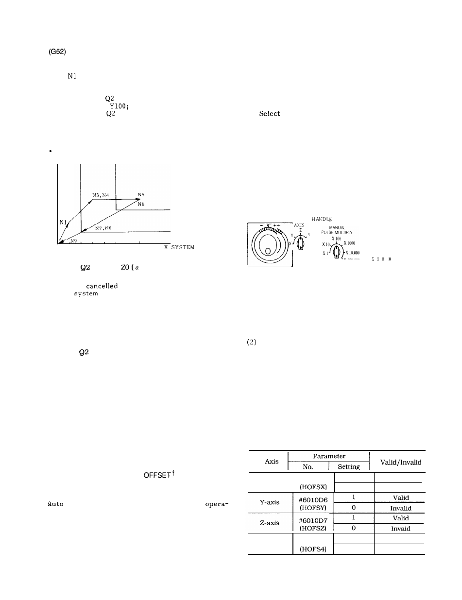
Programming Example
N2
N3
N4
N5
N6
N7
N8
N9
G90 GO1 X1OO Y200 F1OO;
G54;
X l o o Y 3 0 0 ;
G 5 2
X 3 0 0 Y 2 0 0 ;
X 2 0 0
G52
XO YO;
X o Y o ;
G52;
X o Y o ;
Y
400
300
200
100
0
Work Coordinate System Shift Amount (200, 100)
LOCAL COORDINATE
N2
SYSTEM
WORK COORDINATE
SYSTEM
BASIC COORDINATE
100 200 300 400 500 600 700
(2) G52
XO YO
O) ;
When this command is issued, the local coordinate
system is
and return to the work coor-
dinate
occurs.
(3) G52;
By this single block
reference coordinate
(4) Remarks
command, the return to
system occurs.
(a) G52
command is effective only when the work
coordinate system has been set. Alarm “043” occurs if
the command is made under the state of the work coordi-
nate system setting.
(b) Setting of coordinate system by G92 command
or ORG key is not permitted under the state of
setting work coordinate system and local coordinate
system.
(c) Precautions with the setting functions of work
coordinate system are also applicable here.
(d) It should be noted that G52 performs the
operation of canceling the work coordinate system
(G54 to G59) if the above option has not been
added.
2.9.35
AUTO MODE HANDLE
This is the function of synchronizing the movement
by manual pulse generator with the movement by
operation during auto operation (tape
tion, MDI operation, memory operation) .
Deviation due to the mounting of work can be off-
set by this function.
(1) Operating procedures are as follows :
(a) Turn on the auto mode handle offset switch.
(b) Select the axis to be moved by means of the handles
axis select switch. However, if “the manual pulse genera-
tor of simultaneously controllable axes of three-axis con-
trol” has been added, the movement with simultaneous 3
axes can be performed.
(c)
the distance traveled per graduation of
handle by means of manual pulse multiply switch.
The distance traveled per graduation can be
switched to 1, 10 or 100 pulses.
(d) If the handle is turned during the auto
operation of interpolation block, the distance
traveled by handle is synchronized with the
distance traveled by auto operation on the axis
selected by Step (b) .
Clockwise direction:
To positive direction
Counterclockwise direction:
To negative direction
H A N D L E t
‘v’
OFF
L
(e) Turn off the auto mode handle offset switch.
(f) After that the movement is made with the
shift corresponding to the offset made by the
handle.
However, for the setup command (such
as G92) of coordinate system thereafter, the offset
portion by the handle is not added, and the setup
only by the commanded values is performed.
Remarks
(a) Movement of auto mode handle offset is effec-
tive only during interpolation. in auto operation.
It is invalid during rapid traverse or single stop.
(b) Under an alarm state, movement by the auto
mode handIe offset is not possible.
(c) When the axis interlock input (IT) is on,
movement by auto mode handle offset is not pos-
sible.
(d) By means of parameter setting, it is possible
to invalidate the movement by auto mode handle
offset of each axis.
I
#6010D5
1
x-axis
Valid
o
Invalid
#601 1D5
1
4th-axis
Valid
o
Invalid
92