Yaskawa J50M Instructions User Manual
Page 168
4.7.2 SETTING OF DATA INPUT/OUTPUT INTERFACE
TO BE USED (Cent’d)
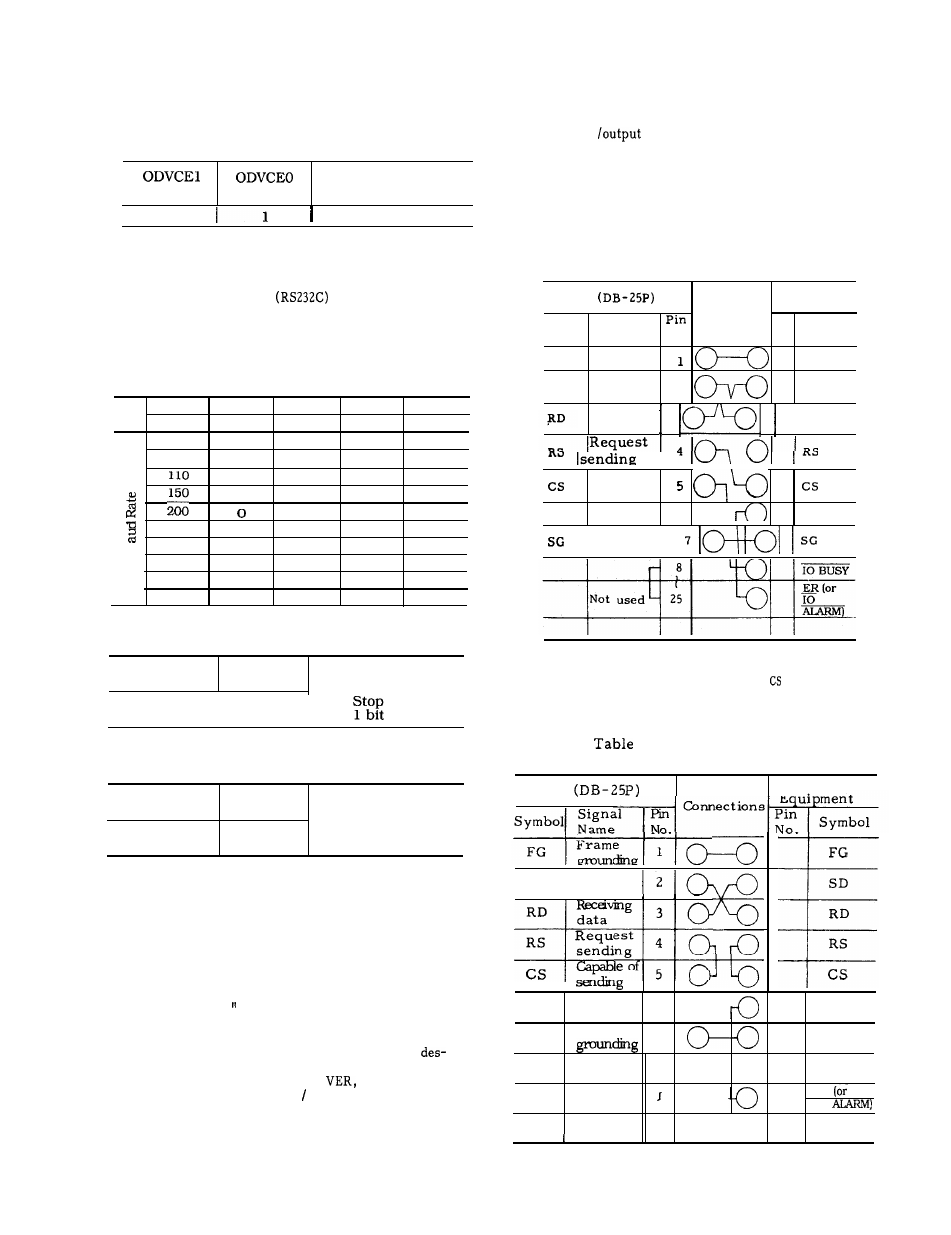
4.7.4 CABLE CONNECTOR SPECIFICATIONS
The specifications of the cable connectors for
data input
interface are as shown in
Tables 4.2 and 4.3.
These specifications depend
on the external equipment to be used and are
therefore listed in this publication for reference
purpose only.
Refer to the manual of the external
equipment.
(2) Setting of Data Output Interface to Be Used
(#6003, D5)
(#6003, D4)
Name of Interface
o
RS232C Interface
Table 4.2
RS 232C Interface
Connecting Cable (A)
External
NC
Equipment
Connections
Signal
Pin
Symbol
Name
No.
No.
Symbol
FG
Frame
grounding
FG
Sending
SD
data
2
‘D
4.7.3 SETTING OF BAUD RATE AND OTHERS OF
SERIAL INTERFACE
To
use
serial interface
, it is nec-
essary to set the baud rate, stop bit length,
and control code transmission specification to
parameters.
a.
Setting of Baud rate
Input
#6026D3
#6026D2
#6026D 1
#6026D0
output
#6028D3
#6028D2
#6028D 1
#6028D0
50
0
0
0
0
100
0
0
0
1
0
0
1
0
0
0
1
1
1
0
0
300
0
1
0
1
al
600
0
1
1
0
1200
0
1
1
1
2400
1
0
0
0
4800
1
0
0
1
Receiving
data
3
‘ D
I
Capable of
sending
Not used
6“
DR
Signal
grounding
I
b. Setting of stop bit length
Note:
When the external equipment does not
control the CS (Capable of Sending) signal given
to NC, short-circuit pins RS and on both
ends of the cable as shown in Table 4.3.
Input
#6026D4
= 1: Stop bit as
2 bits
output
#6028D4
= O :
bit as
4.3
RS
232C
Interface
Connecting Cable (B)
N C
External
C
. Setting of control code transmission designation
Input
#6026D5
= 1 : Does not send
out control code
output
#6028D5
= O : Sends out
control code
SD
RD
RS
Notes:
SD
I
Send:
data
in g
1.
2.
Set the baud rate and stop bit length accord-
ing to the specifications of the input/output
equipment to be used.
The start and stop signals to be sent from
RD
Receiv
data
RS
sendi
I
the
NC
to the inp-ut /output equipment after
pressing IN, VER, or OUT key are called
“control codes.
If the specifications of the
input I output equipment do not allow the
acceptance of the control codes, set the
parameter for control code transmission
ignation to “ 1“ (not send). In this case, it
is necessary to press IN,
or OUT key
on the NC side then start stop the input I
output equipment manually.
Not used
6
DR
SG
Signal
7
SG
‘ 8
ER
IO
Not
used -25
I
I
1
I
160