Yaskawa J50M Instructions User Manual
Page 296

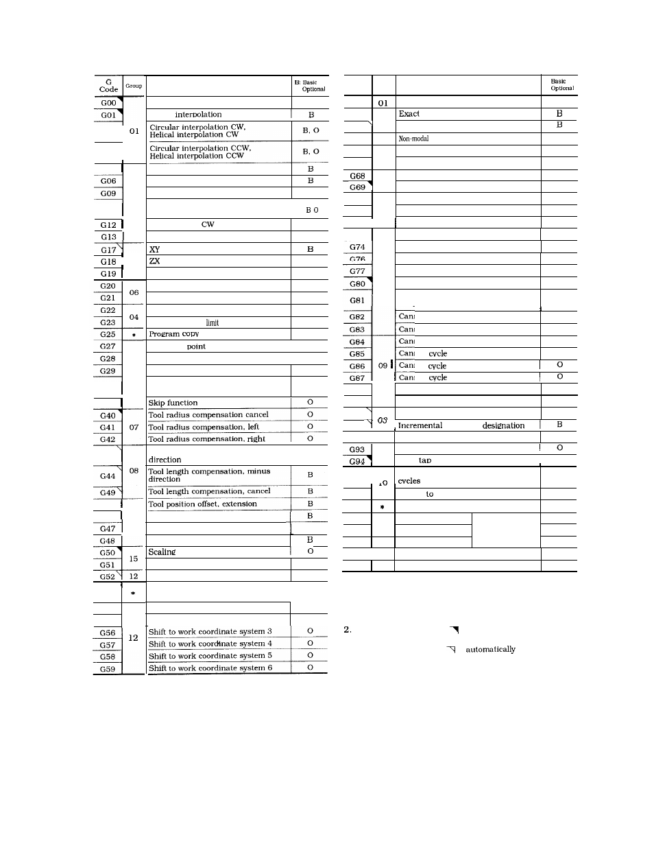
Table A6. 7 List of G Codes
G
B:
Code
Group
Function
0
G60
Unidirectional approach
o
G61
stop mode
13
G64
Exact stop mode cancel
G65
*
call of user macro
o
G66
Modal call
of user macro
o
14
G671
Modal call
of user macro cancel
o
Rotation of coordinate ON
o
18
Rotation of coordinate OFF
o
G70
Bolt hole circle
o
G71
*
Arc
o
“ 0 ” ’
GOO
GO1
Function
0
Positioning
B
Linear
G02
G03
I
G04
Dwell
Positioning
in error detect off mode
Exact stop
E
G06
G09
*
Tool offset value and work coordinate,
Shift-value modification
G1O
I
G72 I
Line-at-angle
o
G73
Circle cutting
o
Circle cutting CCW
o
plane designation
plane designation
B
YZ plane designation
B
Inch input designation
o
Metric
input designation
o
Stored stroke limit ON
o
Stored stroke
OFF
o
o
I
Canned cycle 10
0
Canned cycle 11
0
G74
G76
Canned cycle 12
0
Canned cycle 13
0
I
02
G77
G80 09
Canned cycle cancel
o
Canned cycle 1,
Output for external motion
o
G82
Canned cycle 2
0
G83
G84
G85
G86
09 Canned
6
G87
Canned cycle 3
0
Canned cycle 4
0
Canned
5
0
G27
G28
G29
*
Reference
check
1
0
Automatic return to reference point
1
0
Return from reference point
o
Return to 2nd,
3rd, 4th reference
o
point
Canned
7
I
I
G30
G*8
Canned cycle 8
0
G89
Canned cycle 9
0
G90
Absolute command designation
B
I
G31
Tool radius compensation cancel
Tool radius compensation, left
Tool radius compensation,
G41 07
G42
I
command
G91
1
G92 *
Programming of absolute zero point
o
G93
Solid tap mode ON
05
Solid
mode OFF
Tool length compensation, plus
1’
B
G43
1
0
G44
08
G49
1
G98 ,
Return to initial point for canned
o
Tool length compensation, minus
Tool length compensation, cancel
Tool position offset, extension
.
G99
Return point R for canned cycles
o
G106
Automatic corner override
o
G122
Tool register start
o
17
G123
Tool register end
Tool life control
o
G124
*
Tool register cancel
o
G45
I
G46
Tool position offset, retraction
*
Tool position offset, double extension
B
Tool position offset, double retraction
I
G48
G50
15
G51
G52 12
OFF
G198 *
Form compensation mode ON
o
G199
*
Form compensation mode OFF
o
Scaling ON
o
Return to base coordinate system
o
Notes :
1. The G codes in the * group are non-modal, and are
effective only for the block in which they are commanded.
They cannot be programmed twice or more in a block.
They must be programmed only once in a block of its own.
The codes marked with
is automatically selected at
power on or reset.
3. The codes marked with
is
selected upon
power on.
Temporary shift to machine
coordinate system
L
o
G53
G54
G55
Shift to work coordinate system 1
0
Shift to work coordinate system 2
0
Shift to work coordinate system 3
Shift to work coordinate system 4
to work coordinate system 5
to work coordinate system 6
G56
G57
288
