Yaskawa J50M Instructions User Manual
Page 196
5.2.10 FEED STOP
BY SENSOR
SIGNAL
Turn on the sensor stop switch, to receive the
sensor input signal necessary for centering, groove
width detection step difference designation, and
then to stop.
When the sensor input is on,
operation is not made in the approaching direction,
only in the leading direction.
Therefore,
centering, groove width detection etc.
can also be performed by using this function and
the numerical setting function.
Notes :
(1) The axis that stopped by sensor input will not
move unless once returned in the opposite
direction.
Set this axis return distance in parameter #6578.
set this parameter to prevent sensor
chattering, 1 = pulse)
(2) The sensor stop function is
when the
mode is changed to the automatic mode.
For
safety, it is recommended to keep the sensor away
from the
when changing the mode to
automatic mode.
5.2.11 MANUAL CENTERING FUNCTION
(1)
Call
up the manual mode.
(2)
Select the current screen. “Universal, ”
External. ”
Turn on the sensor stop mode switch.
(4) Specify the centering axis.
WR or the like is then
this
is temporarily stored and
displayed as follows.
x 1 2 3 . 4 5 6
(5)
the X axis and place the sensor on the
circumference of the circle.
The feed stops when
the sensor generates a signal, and the value stored
in (4) is set up at that point.
(6) Move the axis in the opposite direction, and
place the sensor on the circumference of the
reverse side.
The feed stops when the sensor generates a signal,
and the center of the two
points touched
by the
sensor is set up.
(7) Repeat (4) to (6) above
the y
(8) Turn off the sensor stop mode switch.
188
axis.
5.2.12 SPINDLE INDEXING FUNCTION
The spindle indexing function is a function that
stops the spindle at an optional position (a position
with an optional rotary angle) .
5.2.12.1 ADDITIONAL CONDITIONS FOR THE SPINDLE
INDEXING
t
The spindle indexing function must be understood
well, and the conditions consolidated before use.
(a) The S5-digit analog output option must be
incorporated.
(b)
must be mounted on the spindle
drive.
(c) PG must be mounted on the spindle or spindle
motor, and the gear ratio
to be used
at 1 : 1. (The
best performance is gained when the spindle and the
motor are direct-link type).
(d) The number of feedback pulse per spindle rotation
must be 4096.
(e) The solid tap function option must be validated.
5.2.12.2 RELATED PARAMETERS
The following parameters must be preset to use the spin-
dle indexing function. If any change is made to the para-
meters, be sure to turn off the power once.
(1) Spindle PG mounting position
#6065 D7 1: Motor side
o:
Spindle side
Note :
This parameter is used to link the spindle and the
motor with the gear.
Set “O” to use the spindle
indexing function.
(2) Gear ratio of spindle and spindle motor
#6198
Spindle side gears
#6199
Motor side gears
Setting range : to 127
Note :
Set the gear ratio when linking the spindle and
spindle motor with the gear.
Set
both #6198
and #6199 when using the spindle indexing
function.
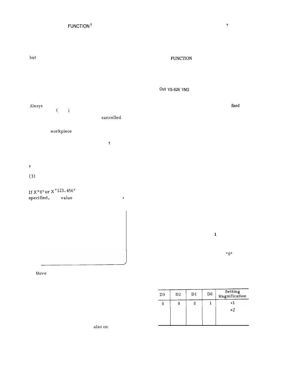
(3) Spindle feedback magnification
#6061 D3 to DO
o
0
1
0
o
1
0
0
x4
1
0
0
0
X
8
Standard setting magnification:
x
4