Appendix-2 list of parameter numbers – Yaskawa J50M Instructions User Manual
Page 221

APPENDIX-2 LIST OF PARAMETER NUMBERS
Parameter numbers
classified in the following
five groups:
Table A2. 1
Parameter number
G r o u p
#6005 to #6099
Setting by bit
#6100 to #6199
Setting
byte
#6220 to #6499
Setting by word
#6600 to #6699
Setting by double words
#7000 #7099
Setting
byte for sequencer
Optimum data of parameters have been set accord-
ing to machine performance and applications. For
any modification of parameter data, consult the
machine tool builder.
Data pertaining to parameters #6033 to #6049 must
not be modified, for they have been incorporated
as part of the system.
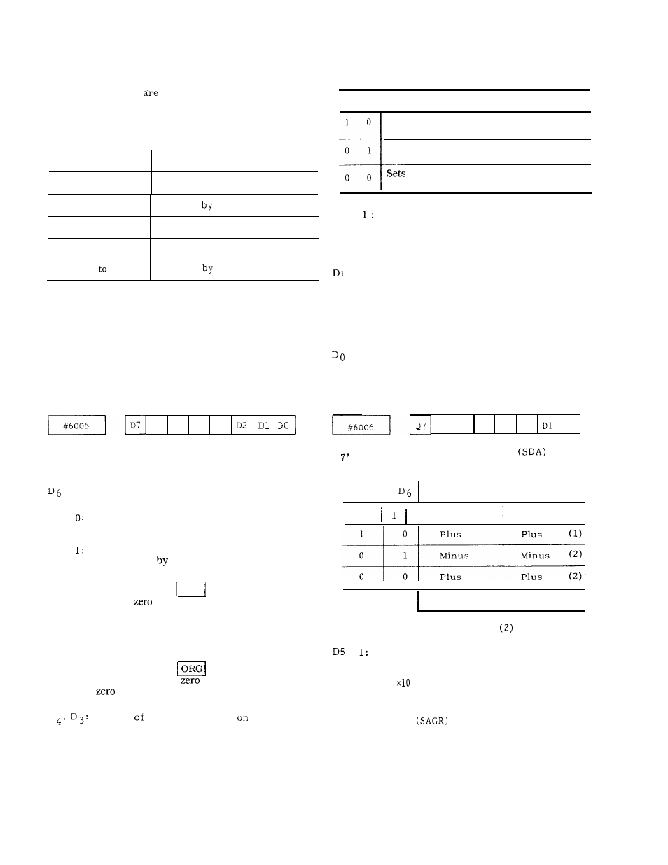
PARAMETER NUMBERS AND THEIR CONTENTS
D6
D5
D4
D3
D7 1:
Stores the H code at G28 for reset.
o:
Sets H code to HOO at
G28
for reset.
1:
D5
0:
D
Stores
the G code in the 01 group for
reset.
Sets the G cede in the 01 group to GOO
for reset.
Allows the current value display (universal)
to be preset
the coordinate system
setting command G92.
At this time, the ORG key has coordinate
system
setup function only in manual
mode.
Keeps the current value display (universal)
from being preset by the coordinate system
setting command G92.
At this time, the
key does not have
coordinate system
setup function while
clear is valid in all modes.
Status
G codes at power
.
D4
D3
Initial status
1 0
0 1
0 0
Sets the G code in the
08
group to G44 at
power on.
Sets the G code in the
08 group to G43 at
power on.
the G code in the 08 group to G49 at
power on.
D2
M95 mode [mirror image ON) at power on
or reset
O : M94 mode (mirror image OFF) at power on
or reset
1: Does not apply mirror image in the G28
interim point in the G95 mode at power on
or reset.
o :
Applies mirror image in the G28 interim
point in the G95 mode at power on or
reset.
1: Sets the G code in the 05 group to G91 at
power on.
O: Sets the G code in the 05 group to G90 at
power on.
D6
D5
D4
D3
D2
DO
D
D
6
Signs of S5-digit analog
output
D7
Sign
‘
Minus
Minus
(1)
at M03 output
at M04 output
Note:
The functions of (1) and
are the same.
D4
Sets the least input increment
x1O
o:
Does not
set the least input increment
to
1: Checks to see if the spindle speed match
signal
is
off upon transition
from a rapid traverse block to a cutting
feed block.
O: Provides no check on the spindle speed
match signal (SAGR) .
213
