Yaskawa J50M Instructions User Manual
Page 131
Additional Explanation
1. G93M turns on when G93 block is executed with
Dry Run OFF and Auxiliary Function Lock OFF.
2, G93M turns off when G94 block is executed or
reset.
3. G93 block completes as SLPS turns on and job
proceeds to next block.
4. G94 block completes as SLPS turns off and job
proceeds to next block.
(2) Solid Tap and Its Relation with Spindle 1/0
During solid tap mode, previous output of gear
select output and SF output ‘is held.
Gear select
input, gear shifting input and spindle orientation
input are disregarded.
If there is more than one gear,
and execute G93
after selecting the gear to be used for solid tap.
(3) Connection to Spindle Pulse Generator
I n t h e s o l i d t a p , t h e s p i n d l e r e v o l u t i o n i s
controlled by using the spindle pulse generator
(hereinafter called “spindle PG” ). Consequently,
both revolving direction of spindle motor and
feedback signal direction from spindle PG have to
be synchronized.
For this purpose, if the spindle PG is not mounted to the
motor and revolving direction of spindle motor and
spindle PG are different, change the connection to phases
A and B as shown in the Connecting Manual.
If both revolving directions are the same, connect them
as shown in the Connecting Manual.
2.12.5
SOLID TAP RELATED PARAMETER
mark below shows the need for power on/off after
setting parameter.
* ( 2 )
(3)
* ( 4 )
Spindle Override in G84
# 6 0 0 7
O : V a l i d
1:
Invalid (completely fixed)
Note :
Override is valid at the time of reading
and it cannot be changed over
during tapping.
Operation at G93
# 6 0 5 5
O:
Spindle not indexing
1:
Spindle indexing
GOO Error Detect in Solid Tap
#6065 DO O:
Error Detect on
1:
Error Detect off
Display of Simultaneous Error Peak
in Solid Tap
# 6 0 6 5
Not display the peak of simul-
taneous error for spindle and
Z-axis
1:
D i s p l a y t h e p e a k o f s i m u l -
taneous error for spindle and
Z-axis
* ( 5 )
* ( 6 )
During solid tap, plus
peak’ of simul-
taneous error is displayed to X-axis error
pulse display area and minus (-) peak of
simultaneous error is displayed to Z-axis
error pulse display area.
Spindle PG Mounting Position
#6065 D7 O:
Spindle side
1:
side
Note:
This parameter is used when a gear
ratio exists between the spindle and motor.
If the ratio is 1:1, set O even if it is at the
motor side.
Gear Ratio between Spindle and Spindle Motor
when Using Solid Tap
#6198 Range : 0 to 127
Number of teeth at spindle side :
n, unit : 1
#6199 Range : 0 to 127
Number of teeth at motor side :
m, unit :
:
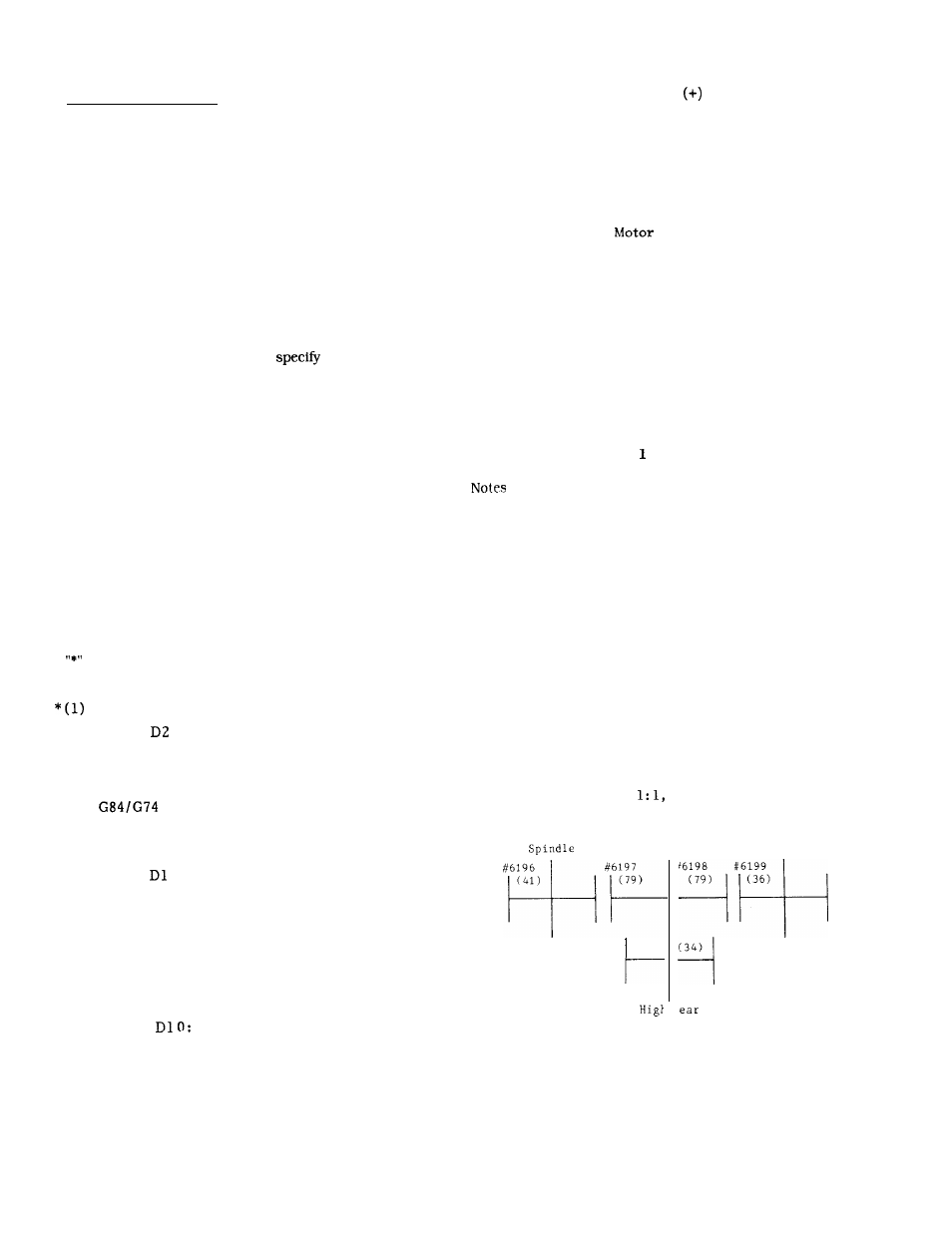
1. It can be set with #6169 or #6197 at the time of using
intermediate gear. Set O to #6196 and #6197 for the
machine not using an intermediate gear (Fig. 1 shows
setting sample).
#6196 Range : 0 to 127
Number of teeth at spindle side
#6197 Range : 0 to 127
Number of intermediate gear teeth at
spindle side
#6198 Range : 0 to 127
Number of intermediate gear teeth at
motor side
#6199 Range : 0
to
1 2 7
Number of teeth at motor side
2. It sets the gear tooth ratio if there is a gear
between the spindle and motor. If spindle:
motor=n: m, set the value of n and m to #6198
and #6199.
If it is
set O both to #6198
and #6199 (it can be as 1, 1) .
Intermediate
Motor
gear
(34)
#6199
(79)
(36)
(34)
123