Yaskawa J50M Instructions User Manual
Page 173

5.1.2 CYCLE START PUSHBUTTON AND LAMP
Depress this pushbutton to start the system in
the automatic operation mode (TAPE, MD I and
MEM) .
The CYCLE START indicating lamp lights
when automatic operation starts.
Depress it again
to start the operation after temporary stop by
pressing FEED HOLD pushbutton or MODE SE-
LECT switch.
5.1.3 FEED HOLD PUSHBUTTON AND LAMP
When the FEED HOLD pushbutton is depressed
during automatic operation , the feedrate is de-
creased immediately and machine motion is stop-
ped.
is not active during tapping by
G84, however, it functions during positioning
before tapping.
If it is depressed while M- , S- , T or
-
tion without move command is being executed,
the FEED HOLD lamp will light, but these func-
tions will be continued until finished. On com-
pletion of the function, the lamp goes off and
machine operation is stopped. Depress the CY-
CLE START pushbutton to resume the operation
after temporary stop by operating FEED HOLD
pushbutton.
FEED HOLD lamp is automatically illuminated when the
machine stops temporarily during canned cycles if SIN-
GLE BLOCK switch is set on, which indicates the opera-
tion is during canned cycle.
5.1.4 EMERGENCY STOP PUSHBUTTON
Depress this pushbutton to immediately stop
machine
movement in an emergency.
servo power is turned
off and the machine is stopped immediately by dynamic
brake. The NC ALARM lamp lights and alarm code “330”
is displayed.
To recover the system from an emergency stop
after the cause has been removed, take the fol-
lowing procedure.
Turn the EMERGENCY STOP pushbutton
clockwise to release the locking.
2.
Depress the RESET key. Alarm code “330’ is changed
to “31 O”.
3.
Turn on the servo power again by depressing POWER
ON pushbutton.
on the
is extinguished
and
lamp lights up.
EMERGENCY STOP
5.1.5 HANDLE
(SIMULTANEOUS ONE-AXIS
CONTROL MANUAL PULSE GENERATOR)
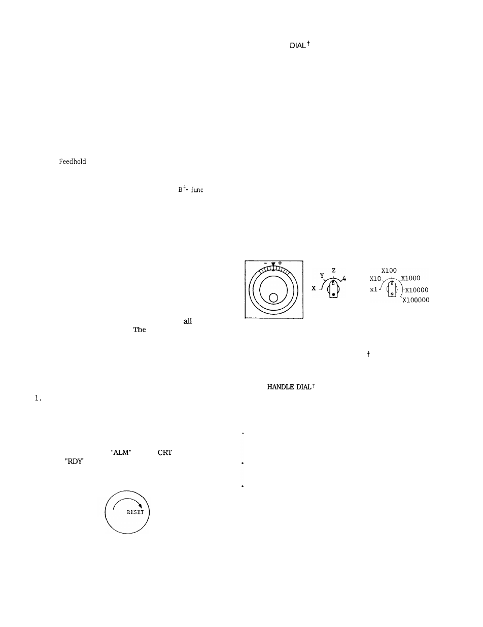
The dial is used as a manual pulse generator to feed the
tool manually with the MODE SELECT switch set to the
HANDLE. After selecting the HANDLE mode, the
machine moves in the plus or minus direction according
to the rotating direction by turning this HANDLE.
Use the axis changing switch for simultaneous one-axis
control. Procedure of HANDLE operation is as follows :
1.
2.
3.
4.
Set the MODE SELECT switch to the HANDLE,
Select the axis to be operated with HANDLE
AXIS select switch.
Set the move amount per graduation of the
dial by setting MANUAL PULSE MULTIPLY
switch.
Rotate the dial to move the selected axis.
Turning it clockwise causes the axis to move
in the plus direction.
The axis moves in the
minus direction by turning it counterclock-
wise.
HANDLE
HANDLE
MANUAL
AXIS
PULSE MULTIPLY
Fig. 5.4
5.1.6
HANDLE AXIS SELECT SWITCH
This switch is used to select and axis to be oper-
ated.
For operation of the switch, see Paragraph
5.1.5
5.1.7
MANUAL PULSE MULTIPLY SELECT SWITCH
t
This switch is used to:
Select the value from Table 5.1, corresponding to a
single graduation of the HANDLE dial in the HANDLE
mode.
Pulses x1OO can be multiplied by any multiplication
factor using parameter #6383.
Select the move amount ( 1 step) from Table
5.2 corresponding to each depression of JOG
pushbutton in the STEP
m o d e .
Fig. 5.3
165
