Ection, Etwork, Nputs – NewTek TriCaster Advanced Edition User Guide User Manual
Page 98
Page | 86
TriCaster makes it easy for you to adjust the Tracker settings by making it possible to see the result of your
attempts in its monitors. Right-click on a monitor and select Tracking Markers from the Overlays options
group in the menu. A yellow-shaded rectangle is overlaid on the video using the current settings. Watch how
this overlay is affected by adjustments you make to the Tolerance value for the Tracker. Raise or lower the
Tolerance value until the result is steady, not jittering or jumping about.
S
MOOTHNESS
The Smoothness setting works just like the LiveMatte feature with the same name. Its impact on tracking
data output is minimal, but it is often important when used with the Advanced Tracking effect in M/E panels
(see Section 14.2.2).
L
OCK
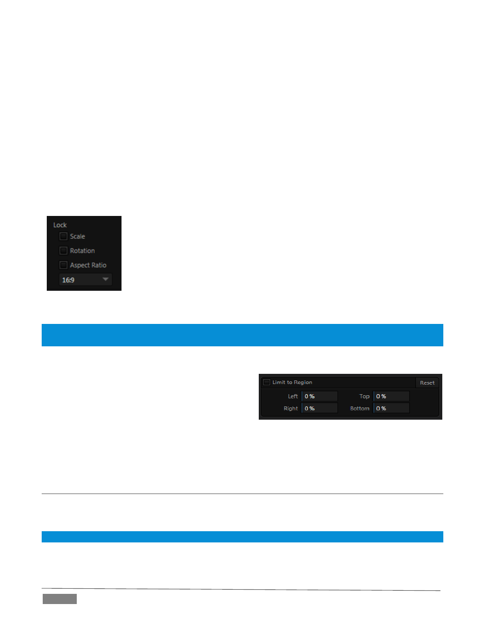
At right are controls that permit you to Lock certain Tracker attributes (Figure 80):
FIGURE 80
Lock Scale to prevent the Tracker from automatically compensating when the
scale of the tracked region grows or shrinks during motion.
Likewise, when Rotation is locked, the orientation of Tracker output is
constrained.
The Aspect Ratio lock forces the Tracker to conform to a square (1:1), or
rectangular (4:3 or 16:9) shape.
Hint: Generally, locking channels in this manner make it easier to obtain a very steady motion track; but just as
often, your choices will be dictated by creative requirements.
L
IMIT TO
R
EGION
The Tracker is designed to follow the largest shape in a
frame that meets the defined color criteria.
At times, similar colored articles or inclusions in the
frame can interfere with Tracker output. The settings in
this group allow you to limit the area of the frame the Tracker monitors,
which can help you sidestep this issue.
We’ll discuss the application of the Tracker’s data stream when discussing the Positioner tools.
SECTION 8.3
NETWORK INPUTS
TriCaster features two dedicated network video inputs, designated Net 1 and Net 2 in the interface and on
the control surface.
Hint: Like other sources, Net 1 and 2 can be renamed.
A wide variety of sources can be supplied to Net inputs, making them exceptionally versatile. In addition,
some sources support special connection features that permit two way communication and control.
FIGURE 81