NewTek TriCaster Advanced Edition User Guide User Manual
Page 174
Page | 162
For TriCaster purposes, an output may be physical, or virtual – i.e., it may involve a connector on the rear
panel, or not. For example, the audio recorded by TriCaster does not necessarily require an output connector.
Note: TriCaster Mini’s audio inputs and outputs are stereo. Audio can be routed to the Master 2 and Aux 2 busses,
however, for internal use (i.e., sound on these tracks will be captured if you configure an Isocorder recording to
include them).
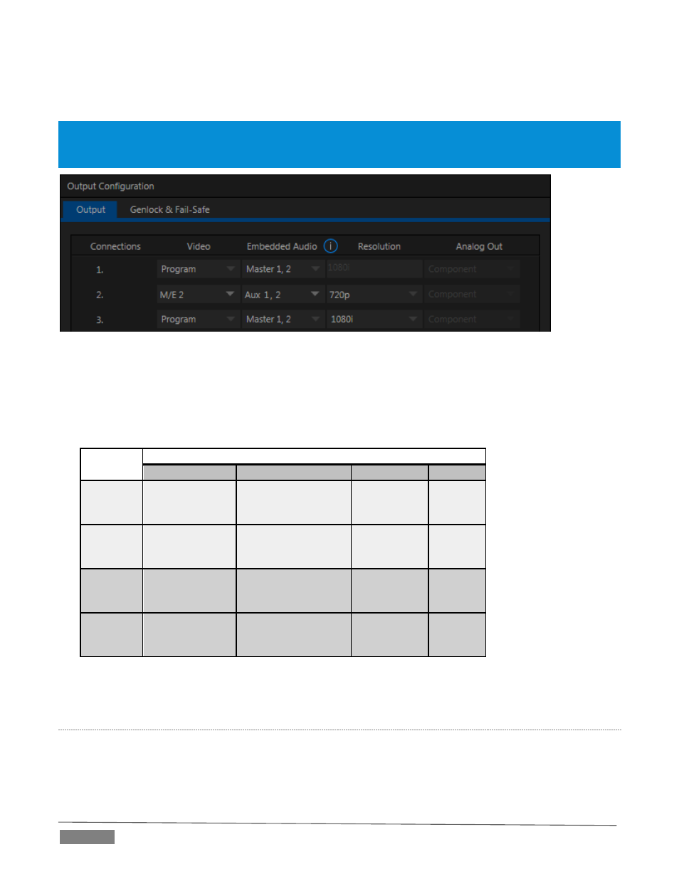
FIGURE 204
Likewise, it may be analog or digital. Analog Outputs 1 and 2 (note that Output 2 is not a TriCaster Mini
feature) are permanently assigned to “Master 1, 2”, and “Aux 1,2”, respectively .
In contrast, digital (or ‘embedded’) outputs are configurable. By default, the sound from the primary busses
is routed to physical outputs as shown in the following table (support varies by model). See Figure 204.
Bus
Output Connectors
Analog Outputs
SDI Outputs
AES Outputs
HDMI
Master 1
1a, 1b
(Mini: L, R)
1 (channels 1 & 2)
3 (channels 1 & 2)
1a,b
(8-input
models)
1
Master 2
1c, 1d
(8-input
models)
1 (channels 3 & 4)
3 (channels 3 & 4)
1c,d
(8-input
models)
Aux 1
2a, 2b
(All except
Mini)
2 (channels 1 & 2)
2
Aux 2
2c, 2d
(8-input
models)
2 (channels 3 & 4)
Again, the standard mapping of video outputs can also be modified to suit your specific needs – See Section
8.1, Output Configuration.
S
UB
-M
IXES AND
‘M
IX
M
INUS
’
At times you may require specially configured audio mixes, typically using one of TriCaster’s two stereo Aux
audio outputs. For instance – some installations call for sending audio from one or more internal sources
(such as a DDR or the Sounds player) to a secondary distribution system.