Okidata 184 setup – Gasboy 1000 Series FMS Operation Manual User Manual
Page 231
Setup of Peripheral Equipment
05/29/03
B-3
6.
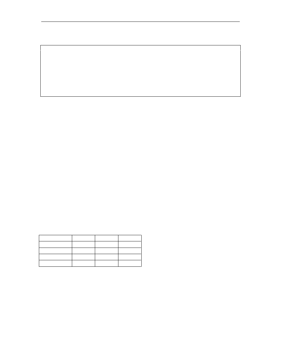
Press F5 or PAGE DOWN to display the next Setup Screen, ANSI Setup.
7PUEÂUsÂ
Â
Â
BGsÂHqyÂ
QttÂ
UsrÂ
7Â
Â
BsisÂHqyÂ
QttÂ
RwÂ
PiwiÂ
Â
GsirÂ
PswqÂ
UsrÂ7siÂ
UqssÂ
Â
9ÂGsÂ
PiÂ
RwÂ7siÂ
UqssÂ
Â
`tsÂVsÂ
AQUÂ
UsrÂVsÂ
PsÂ
Â
9viÂIrsÂ
IwiwiÂ
RwÂVsÂ
PsÂ
Â
9viÂUsÂ
@A9I9UÂ
RwÂIrsÂ
7Â
Â
GsÂ
VswsÂ
7Â7spiqyÂ
QttÂ
Â
XV! ÂE@Â
XVÂ! Â
Â
7. Press
S to save Setup changes.
8.
Press F9 or E to exit Setup Mode.
OKIDATA 184 SETUP
To prepare the Okidata printer for operation with the LINK MC5 terminal and your GASBOY Fuel
Management System, perform the following steps. Install and complete the setup of the printer as
specified in the manufacturer’s setup instructions. Then set up the switches as follows:
SW1
SW1-1 ON
Parity: Odd
SW1-2 ON
Parity: Without
SW1-3 ON
Data bits: 8
SW1-4 OFF
Protocol: XON/XOFF (Series 1000 V8.1 or higher)
ON
Ready/Busy (Series 1000 versions prior to V8.1)
SW1-5 ON
Test select: Circuit
SW1-6 ON
Mode select: Print
SW1-7 ON
Busy line selection: DTR - Pin 20
SW1-8 ON
Busy line selection: DTR - Pin 20
SW2
Baud
Rate SW2-1 SW2-2 SW2-3
9600 OFF
ON
ON
2400
OFF OFF ON
1200
ON ON OFF
300 ON
OFF
OFF
NOTE: Any change made to the baud rate must also be changed on the Link terminal
Communications Setup screen, Aux Baud parameter.
SW2-4 ON
DSR output signal: Active
SW2-5 ON
Buffer threshold: 32 bytes
SW2-6 OFF
Busy signal timing: 1 sec (min.)
SW2-7 ON
DTR signal: Space after power on
SW2-8 OFF
Not used