Gasboy 1000 Series FMS Operation Manual User Manual
Page 22
GASBOY Series 1000
3-2
05/29/03
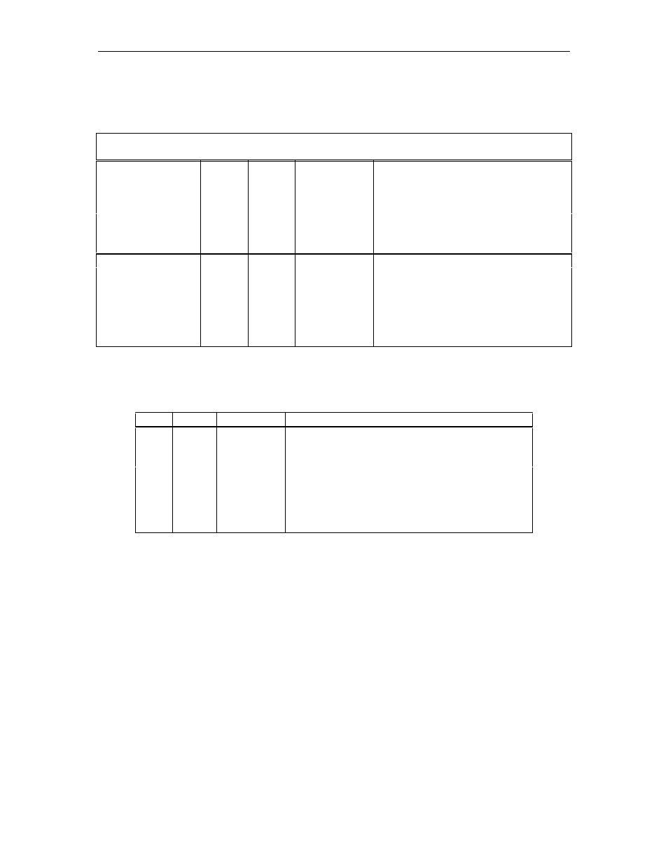
COMMUNICATION TERMINATIONS
The wiring terminations for the various communication options are indicated below:
System
TB
Signal
System
I/O
Notes
RS-232
1
TXD
output
Transmitted data out of system
2
DTR
output
Data terminal ready out of system
3
RXD
input
Received data into system
4
DCD
input
Data carrier detect into system
5
GND
ground
Signal ground reference
RS-422
1
TX+
output
Transmitted data out of system
2
TX-
output
3
RX+
input
Received data into system
4
RX-
input
5
N/A
--
Pinout of GASBOY Short Haul Modem RS-232 Connector
Pin Signal SHM
I/O
Notes
2
TXD
input
Transmitted data into modem
3
RXD
output
Received data out of modem
7
GND
ground
Signal ground reference
8
DCD
output
Data carrier detect out of SHM
20
DTR
input
Data terminal ready into SHM
NOTE: Pins 5 and 6 are tied to Pin 8 internally.
TB=Terminal block
PIN=PIN connection on RS-232 connector
I/O=input/output