1 cdmr-570al – apply dc power – Comtech EF Data CDM-570A User Manual
Page 83
CDM-570A/570AL Satellite Modem with Optional Packet Processor
MN-CDM570A
Rear Panel Connectors and Pinouts
Revision 2
3–21
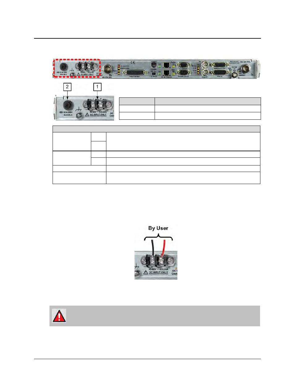
3.3.3.3 CDMR-570AL Reduced Chassis Depth Modem -24 or -48V DC
Power and Fuse
DC Power Specifications (with CnC, without optional Packet Processor)
Input Power
-48V
•
Without optional Packet Processor or CnC: 29W typical, 32W maximum
•
With optional Packet Processor, without CnC: 42W typical
•
With optional Packet Processor and CnC: 48W maximum
-24V
Input Voltage
-48V 48V DC nominal (43-60V)
-24V 24V DC nominal (20-36V)
Connector Type
Terminal Block
Fuse Protection
Use one (1X) TR5 6.3A 20mm Slo-Blo fuse for ALL units (with or without BUC). The
fuse is contained within a screw-in receptacle located to the left of the terminal block.
Figure 3-12. CDMR-570AL Reduced Chassis Depth Modem -24 or -48V DC Power
(CDMR-570AL-IP Shown)
3.3.3.3.1 CDMR-570AL – Apply DC Power
Figure 3-13. Apply DC Power to the CDMR-570AL
Do these steps (Figure 3-13):
WARNING! ENSURE THAT THE POWER IS REMOVED FROM THE DC CIRCUIT BEFORE
PROCEEDING!
1.
Use a screwdriver to affix the user-supplied DC power leads to their respective terminals.
Number 18 AWG minimum wires are recommended.
Feature
Description
1
Power Terminal Block
2
Screw-in Fuse Holder / Receptacle