Calibrating displacement, Zeroing the displacement – Dr. Livingstone, I Presume WELDWISE 2400 User Manual
Page 109
0435-INS-400
Rev.
D
8-5
Calibrating Displacement
Livingston strongly recommends fabricating two different gauge blocks that fit into the welding
electrodes for displacement calibration. Typically, these blocks are made of hardened steel. The first
block should be equal to the stack-up thickness of the parts to be welded. The second block should
have a known thickness that is not more than 4.5% of the overall stroke of the sensor. For example, a
gauge block for a sensor with a 4-inch stroke should be of a thickness generally around half and no
greater than 0.180 inches.
These blocks can be chained to the machine for easy access.
To calibrate the displacement:
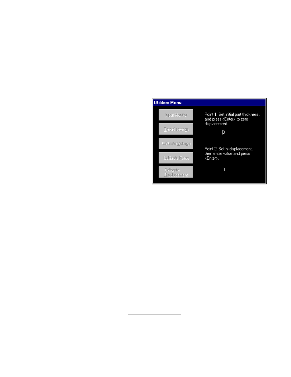
1. From the Utilities Menu, choose the Calibrate
Displacement option.
2. Place a gauge block equaling the stack-up
thickness of the parts to be welded between the
weld head electrodes. Close the weld head
electrodes on the gauge block.
3. Enter '0' for the Point 1 value and press ENTER.
(This does exactly the same thing as the Zero
Displacement Button. Refer to the section
below for more details).
4. Open the weld head electrodes and add a second
gauge block of known thickness on top of the first block. Close the weld electrodes onto the blocks
and enter the known thickness of the gauge block as the Point 2 value and press ENTER.
5. Select ESCAPE to exit the window. Return to the Input Monitor screen and check the readings
both with and without the second gauge block in place. The values displayed should correspond to
those that were entered when calibrating the displacement sensor.
Note
: If it is not possible to position two known thicknesses, calibration may be done with the tips
together. Zero with the electrodes closed together, then use a shim or washer of a known thickness
placed between the electrodes for calibration. Once you have verified the values with the Input
Monitor re-zero with the full part stack-up clamped up.
Zeroing the Displacement
The Zero Displacement button on the Input Monitor screen centers the range of the displacement
readings so that incoming values will be within the appropriate measurement range. The monitoring
program compensates for the incoming voltage readings to establish a mid-range setting at the
appropriate sensitivity. Refer to Chapter 6, WMS Reference Guide for more details.
Figure 8-6 Calibrate Displacement screen