Dr. Livingstone, I Presume WELDWISE 2400 User Manual
Page 103
0434-INS-400 Rev. C
7-9
Figure 7-6 Weld Summary screen
To perform a quick test of the sensor installation:
1. With the sensors connected and the WeldWise™ 2400 turned on, set up the welder as usual to
perform a weld. The monitoring of weld events is triggered by current detection and is preset, so no
further setup is required to begin recording values during welding.
2. Make a few welds.
3. Note the values that appear on the monitor's main program screen. If the parameters CurrentRms
and VoltageRms are not already displayed on the weld monitor's screen, click
any parameter box
on the screen itself, click the SELECT key on the Virtual Key-pad and then use the Arrow Keys to
scroll through the various parameters until CurrentRms is displayed. Press ENTER to show
incoming readings for that parameter. Do the same with another parameter box and select
VoltageRms. The graphic display indicates the levels of the sensor readings for these factors and
these values are recorded for the weld.
Note: Readings will be uncalibrated, as the sensors have not been calibrated yet. Calibration is covered
in Chapter 8, Calibrating the Sensors
4. Click the MENU button on the Key-pad.
5. Select the Data option from the Main Menu.
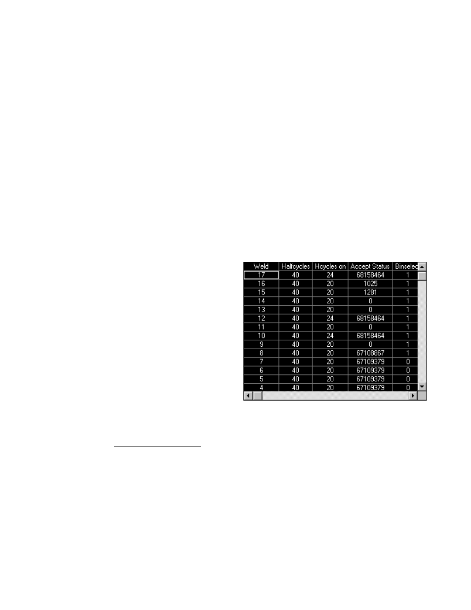
6. Select Weld Summary. The program displays
the data collected for the welds, organized by
weld number, as shown in figure 7-7. For each
weld made, the Halfcycle count should be twice
the amount of cycles in the weld. For example,
a schedule with 5 cycles of Squeeze, 10 cycles
of Weld and 8 cycles of Hold would have 46
total halfcycles (5 + 10 + 8 = 23, 23 times 2 =
46). Use the Arrow Keys to scroll through the
various headings to view readings for Current,
Voltage, Force and Setdown/Expansion
(Displacement).
If any of these operations don't work as described, recheck the setup instructions in this chapter or
consult Chapter 6, WMS Reference Guide.