Rockwell Automation 1441-PEN25-Z Enpac 2500 Data Collector User Manual
Page 241
Rockwell Automation Publication GMSI10-UM002D-EN-E - August 2012
241
Time Recorder Application
Chapter 9
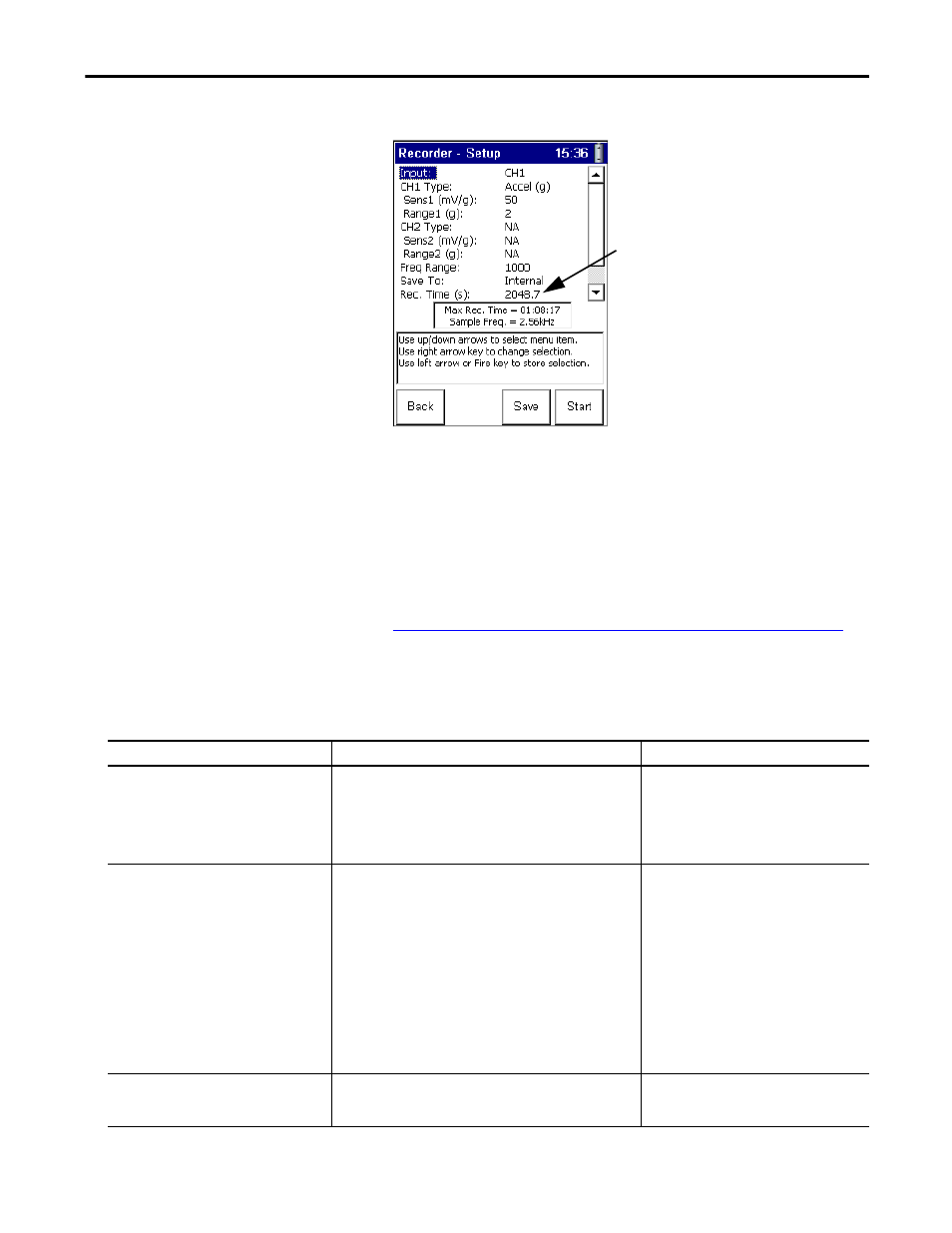
The Recorder - Setup screen appears.
5.
Highlight the parameter and press the RIGHT ARROW key to open the
menu of choices.
6.
Select the choice by pressing the arrow keys, or typing in a value using the
numeric key pad.
7.
Press the LEFT ARROW key to save your choices.
8.
Press F3 (Save) to save the current settings to a file.
Refer to Saving a Time Recorder Setup and Measurement on page 244
.
Use the descriptions in this table to help you configure the Time Recorder
parameters.
Maximum recording time determined by
measurement settings & free space
available on Save To setting.
Table 43 - Time Recorder Setup Parameters
Parameter Name
Description
Values/Comments
Input
The input channel(s) for the recorder measurement.
Important: Your selection affects the Freq Range maximum
frequency setting and the recordings maximum recording time.
• CH1 - 20 kHz maximum Freq Range
• CH1 & CH2 - 10 kHz maximum Freq Range for each channel
• CH1 & Tacho - 10 kHz maximum Freq Range for each channel
Options:
CH1 (default)
CH1 & CH2
CH1 & Tacho
CH1 Type
Sets the vibration measurement type used on CH1.
Your selection determines the available options and engineering units
for subsequent setup parameters.
Options:
Accel (G) (default)
Accel (m/s
2
)
Vel (mm/s)
Vel (ips)
Disp (mils)
Disp (μm)
Volts (V)
Volts AC
Press. (Pa)
Force (N)
Force (lBf)*
Sens1
The sensitivity of the transducer in millivolts (mv) per Engineering
Units for CH1.
The sensitivity value is included with the
transducers documentation or it may be imprinted
on the side of the transducer.