IAI America RCS3PCR-SS8C User Manual
Page 49
2. Specification
40
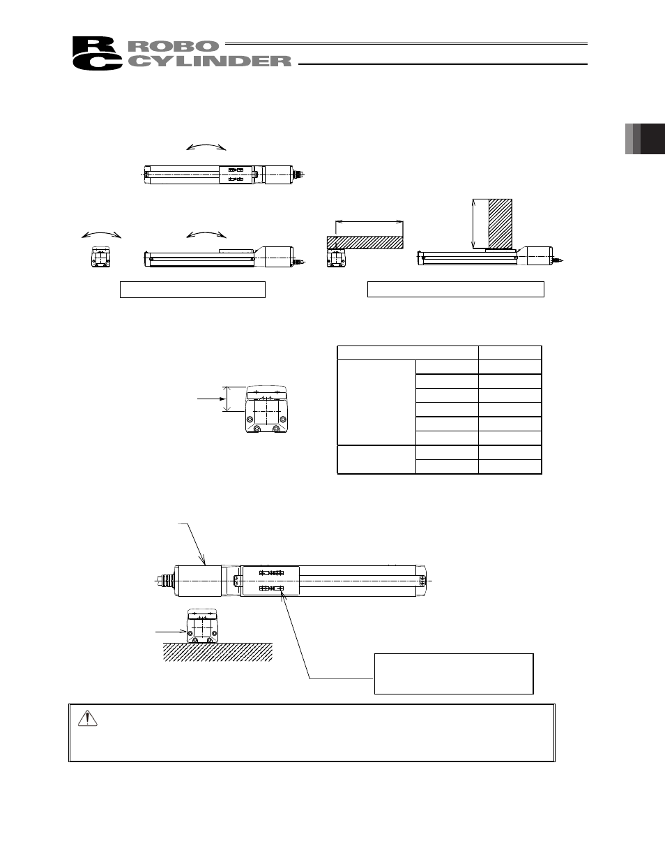
Mb, Mc directions
Ma direction
Directions of moment forces
Directions of allowable overhangs
L
Reference position
��
��
��
�
�
�
RCS2
RCS2CR
SA4�SS4
31.2mm
SA5�SS5
39.0mm
SA6�SS6
40.0mm
SA7
43.0mm
SS7
36.0mm
SS8
48.0mm
RCS3�P�
RCS3�P�CR
SA8
44.0mm
SS8
48.0mm
Y-axis
X-axis
The Ma and Mc moments applying
on this slider should be kept to one-
half the allowable moment.
�
The allowable overhang lengths are based on a configuration where the center of gravity of the load mounted
on the actuator corresponds to the center of the overhang length.
(Note) To calculate the moments in Ma and Mc directions, offset the reference position by L mm from the top
surface of the slider, as shown in the figure below.
If an actuator is used as the Y-axis in a cantilever system based on X-Y combination, its base deforms easily.
Accordingly, keep the Ma and Mc moments to no more than one-half their respective ratings. (See the figure
below.)
Caution: Allowing the slider to receive an excessive load moment will shorten the service
life of the guides. If the allowable overhang length is exceeded, vibration may
generate or the service life of the guides may be reduced.
- RCS3PCR-SA8C RCS3CR-SS8C RCS3CR-SA8C RCS3P-SS8C RCS3P-SA8C RCS3-SS8C RCS3-SA8C RCS2CR-SS8C RCS2CR-SS7C RCS2CR-SA7C RCS2CR-SA6D RCS2CR-SA6C RCS2CR-SA5D RCS2CR-SA5C RCS2CR-SA4C RCS2-SS8R RCS2-SS8C RCS2-SS7R RCS2-SS7C RCS2-SA7R RCS2-SA7C RCS2-SA6R RCS2-SA6D RCS2-SA6C RCS2-SA5R RCS2-SA5D RCS2-SA5C RCS2-SA4R RCS2-SA4D RCS2-SA4C