11 rcs2-sa5r, Appendix 211 – IAI America RCS3PCR-SS8C User Manual
Page 231
12.
Appendix
211
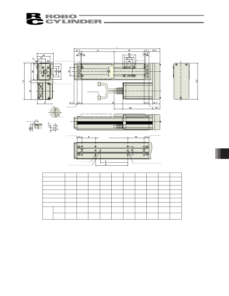
12.1.11
RCS2-SA5R
50
100
150
200
250
300
350
400
450
500
L
215.9 265.9 315.9 365.9 415.9 465.9 515.9 565.9 615.9 665.9
M
142
192
242
292
342
392
442
492
542
592
N
50
100
100
200
200
300
300
400
400
500
P
35
85
85
185
185
285
285
385
385
485
R
42
42
92
42
92
42
92
42
92
42
U
�
1
1
2
2
3
3
4
4
5
m
4
4
4
6
6
8
8
10
10
12
At least 100
or more
Reference
surface
Stroke
4-M4, depth 9
Detail view of A
Home
m-M4, depth 7
Cable joint
connector
Oblong hole, depth 5 from
bottom surface of base
Slider height: 50
Ac
tu
at
or
w
id
th
:5
2
4-�4.5
�
8, deep counterbore,
depth 4.5 (for actuator
installation)
Reference position for
Ma moment offset
Slit
For position
adjustment
�
8 hole
Detail of slit for slider
position adjustment
Detail of oblong hole
(Detail of reference
surface of actuator)
End face of base
End face of base
(pitch of �4 hole and oblong hole)
(pitch of �4 holes)
2- �4H7 Depth 5 from bottom
surface of base
End face of base
(131 with brake)
End face of base
Bottom
surface of
base
50 (stroke 50)
U x 100
P
(stroke other than 50)
(to
le
ra
nc
e
fo
r re
ame
d
ho
le
p
itch
�
0.
02
mm)
Stroke
0
00
0
00
0
00
0
00
0
00
L
.
.
.
.
.
.
.
.
.
.
M
N
0
00
00
00
00
00
00
00
00
00
P
R
U
-
m
0
0
Weight
[kg]
without
brake
.
.
.
.
.
.0
.
.
.
.
with
brake
.
.
.0
.
.
.
.
.
.
.
- RCS3PCR-SA8C RCS3CR-SS8C RCS3CR-SA8C RCS3P-SS8C RCS3P-SA8C RCS3-SS8C RCS3-SA8C RCS2CR-SS8C RCS2CR-SS7C RCS2CR-SA7C RCS2CR-SA6D RCS2CR-SA6C RCS2CR-SA5D RCS2CR-SA5C RCS2CR-SA4C RCS2-SS8R RCS2-SS8C RCS2-SS7R RCS2-SS7C RCS2-SA7R RCS2-SA7C RCS2-SA6R RCS2-SA6D RCS2-SA6C RCS2-SA5R RCS2-SA5D RCS2-SA5C RCS2-SA4R RCS2-SA4D RCS2-SA4C