Appendix, 1 external dimensions, 1 rcs2-sa4c – IAI America RCS3PCR-SS8C User Manual
Page 221: Appendix 201
12.
Appendix
201
50
100
150
200
250
300
350
400
L
279
329
379
429
479
529
579
629
318
368
418
468
518
568
618
668
M
122
172
222
272
322
372
422
472
N
50
100
100
200
200
300
300
400
P
35
85
85
185
185
285
285
385
R
22
22
72
22
72
22
72
22
U
�
1
1
2
2
3
3
4
m
4
4
4
6
6
8
8
10
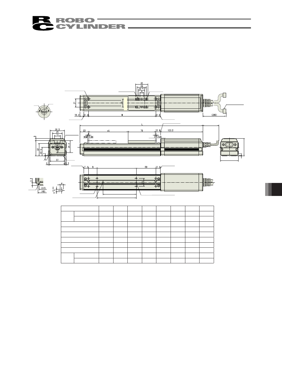
12. Appendix
12.1 External Dimensions
12.1.1
RCS2-SA4C
Stroke
without break
with break
Reference
surface
For position adjustment
Oblong hole, depth 5 from
bottom surface of base
2-�3H7, depth 5
Cable joint connector
At least 100 or more
Detail view of A
(Detail of reference
surface of actuator)
4-M3, depth 7
m-M3, depth 5
Home
2-�3.6
��
6.5, deep
counterbore, depth 3.7
(for actuator installation)
Slit
�
8 hole
Detail of slit for slider
position adjustment
Reference
position for
Ma moment
offset
Sl
id
er
h
ei
gh
t:
40
Actuator width:
Bottom surface of
base
End face of
base
End face of base
50 (stroke 50)
U x 100
P
(stroke other than 50)
End face of
base
End face of
base
End face of base
(162.2 with brake)
Motor width: 46
M
ot
or
h
ei
gh
t:
45
Detail of oblong
hole
P (pitch of �3 hole and
oblong hole)
N (pitch of �3 holes)
(to
le
ra
nc
e
fo
r re
ame
d
ho
le
p
itch
�
0.
02
mm)
2-�3H7 Depth 5 from bottom surface
of base
Stroke
0
00
0
00
0
00
0
00
L
without brake
with brake
M
N
0
00
00
00
00
00
00
00
P
R
U
-
m
0
Weight
[kg]
without brake
0.
0.
0.
.0
.
.
.
.
with brake
.0
.
.
.
.
.
.
.
- RCS3PCR-SA8C RCS3CR-SS8C RCS3CR-SA8C RCS3P-SS8C RCS3P-SA8C RCS3-SS8C RCS3-SA8C RCS2CR-SS8C RCS2CR-SS7C RCS2CR-SA7C RCS2CR-SA6D RCS2CR-SA6C RCS2CR-SA5D RCS2CR-SA5C RCS2CR-SA4C RCS2-SS8R RCS2-SS8C RCS2-SS7R RCS2-SS7C RCS2-SA7R RCS2-SA7C RCS2-SA6R RCS2-SA6D RCS2-SA6C RCS2-SA5R RCS2-SA5D RCS2-SA5C RCS2-SA4R RCS2-SA4D RCS2-SA4C