23 rcs2cr-sa6d, Appendix 223 – IAI America RCS3PCR-SS8C User Manual
Page 243
12.
Appendix
223
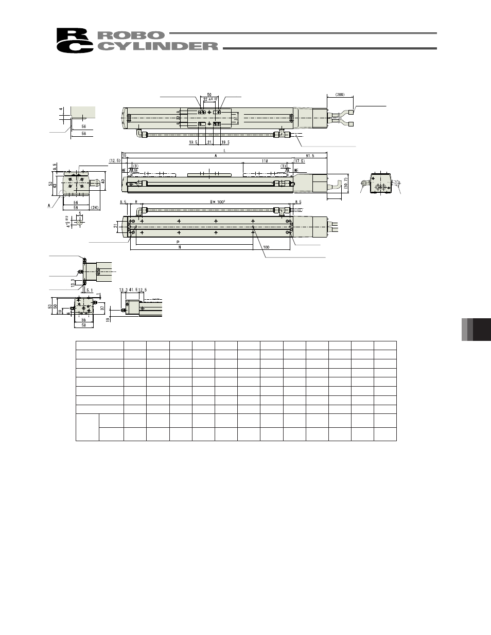
12.1.23
RCS2CR-SA6D
50
100
150
200
250
300
350
400
450
500
550
600
L
304.5 354.5 404.5 454.5 504.5 554.5 604.5 654.5 704.5 754.5 804.5 854.5
A
198
248
298
348
398
448
498
548
598
648
698
748
N
81
131
181
231
281
331
381
431
481
531
581
631
P
66
116
166
216
266
316
366
416
466
516
566
616
R
81
31
81
31
81
31
81
31
81
31
81
31
U
1
2
2
3
3
4
4
5
5
6
6
7
m
6
8
8
10
10
12
12
14
14
16
16
18
Stroke
Opposite side
(option)
2-�5H7, depth 6
Cable joint
connector
4-M5 depth 9
At least 100 or more
Home
Stroke
m-M5 depth 8
(to
le
ra
nc
e
fo
r re
ame
d
ho
le
p
itch
�
0.
02
mm)
Oblong hole,
depth 5 from
bottom surface of
base
R: Brake cable exit
from right
E: Brake cable
exit from end
L: Brake cable
exit from left
(pitch of �4 hole and oblong hole)
(pitch of �4 holes)
(pitch of �4
holes)
ME: Mechanical End,
SE: Stroke End
Standard side
Applicable tube outer diameter: �8
Reference
surface
Reference
position for
Ma moment
Brake Dimensions
3-�4H7 Depth 5 from bottom
surface of base
Detail of oblong hole
Stroke
0
00
0
00
0
00
0
00
0
00
0
00
L
0. . 0. . 0. . 0. . 0. . 0. .
A
N
P
R
U
m
0
0
Weight
[kg]
without
brake
.0
.
.
.
.
.
.
.0
.
.
.
.
with
brake
.
.
.
.
.
.0
.
.
.
.
.
.
- RCS3PCR-SA8C RCS3CR-SS8C RCS3CR-SA8C RCS3P-SS8C RCS3P-SA8C RCS3-SS8C RCS3-SA8C RCS2CR-SS8C RCS2CR-SS7C RCS2CR-SA7C RCS2CR-SA6D RCS2CR-SA6C RCS2CR-SA5D RCS2CR-SA5C RCS2CR-SA4C RCS2-SS8R RCS2-SS8C RCS2-SS7R RCS2-SS7C RCS2-SA7R RCS2-SA7C RCS2-SA6R RCS2-SA6D RCS2-SA6C RCS2-SA5R RCS2-SA5D RCS2-SA5C RCS2-SA4R RCS2-SA4D RCS2-SA4C