Luminex 100 IS User Manual, Version 2.1 User Manual
Page 55
x
MAP Technology
System Calibration
PN 89-00002-00-061 Rev. A
6 - 3
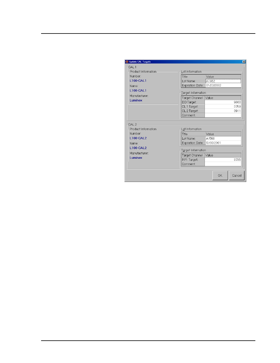
Figure 21. Update Calibration Targets Dialog Box
10. Enter the values listed from the Certificates of Analysis included
with your calibrators into the CAL1 and CAL2 entry fields.
11. Click OK. The dialog box disappears.
12. Ensure that the IS is set to draw the CAL1 and CAL2 beads from
the wells where you loaded them (in step 2).
13. Click CAL1 from the Maintenance tab. A Confirmation Screen
dialog box appears.
14. Click OK and wait until CAL1 completes. The device status
section in the status bar changes from “Running” to “Standby”.
15. Click CAL2 from the Maintenance tab. A Confirmation Screen
dialog box appears.
16. Click OK and wait until CAL2 completes. The device status
section in the status bar changes from “Running” to “Standby”.
You must run system controls following calibration. Continue on to
the “Run System Controls” on page 6-4.
Note:
Ensure that you enter
the correct target values for
each parameter before clicking
OK. If necessary, re-enter the
information to correct any
incorrect information.
Note:
The message log on the
Diagnostics tab shows the
status of the CAL1 and CAL2
commands. If an error occurs
during system calibration, the
Diagnostics tab turns red.