Figure 35, Pico/e-32 switches in test mode, Figure 36 – Clear-Com Eclipse-Omega User Manual
Page 46: E-32 boot output, Eclipse upgrade reference manual
Eclipse Upgrade Reference Manual
Clear-Com Communication Systems
Page 46 of 155
Part Number: 810377Z Rev 6
COM1:
(change to match a COM port present on the PC)
Baud Rate: 115200
Parity:
Even
Data Bits:
8
Stop Bits:
One
8. Connect the serial communications lead between the PC serial port and the
RS232 port on the front of the matrix.
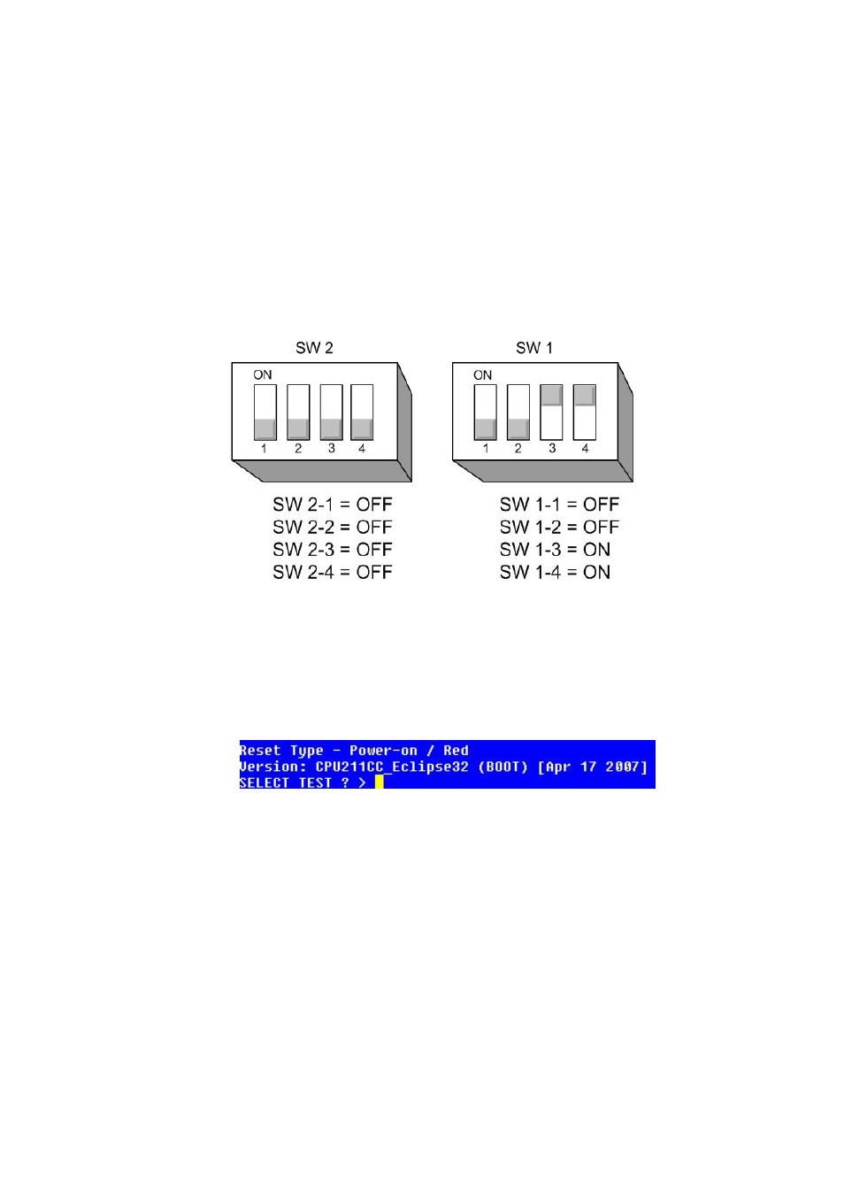
9. Set the board DIP switches into Test mode as shown below:
Figure 35 - PiCo/E-32 Switches in Test mode
10. Power cycle or reset the E32/Pico so that the DIP switch changes come into
effect.
11. Confirm that the Configuration card has entered test mode. You should see the
following display:
Figure 36 - E-32 Boot Output
• Note that sometimes you may need to hit the return key a few times
to get this screen to come up.
• You can press "?" to see all available options in the test mode.
• You can press "i" to see that all current application that is loaded on
the CPU.
12. On the keyboard press number 1 then press [enter] or [return] to start the
erase of Flash. Confirm that you want to erase Flash by selecting ‘y’ and press
[enter]. (Erasing Flash will take approximately 1 minute to complete) and is
followed by a considerable number of “Sector Erase” messages.
13. Once the flash erase is complete, press number 2 then press [enter] or [return]
to start the erase of NVRAM. This will generate”RAM Test” messages.