B&B Electronics VFG3000 - Manual User Manual
Page 34
S
LAVE
P
ROTOCOLS
V
LINX
F
IELDBUS
G
ATEWAY
M
ANAGER
U
SER
M
ANUAL
P
AGE
18
Note that a single device has been automatically created for the protocol. In the case of master
protocols, this represents the remote device that the Gateway will access. In this case, though,
the device represents the Modbus slave that the Gateway will itself embody. This means that
only a single device is required, and that things such as the station number to which the
Gateway will respond are normally configured via the port settings rather than those of the
device.
A
DDING
G
ATEWAY
B
LOCKS
Having configured the protocol, you must now decide what range of addresses you want the
slave protocol to expose. In this example, we want to use Modbus registers
40001
through
40008
to allow read and write access to certain data items in our database. We begin by
selecting the device icon in the left-hand pane of the Communications window, and clicking
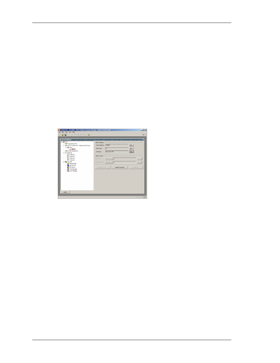
the Add Gateway Block button in the right-hand pane. An icon to represent Block 1 will
appear, and selecting it will show the following settings…
In the example above, we have configured the Start Address to
40001
to indicate that this is
where we want the block to begin. We have also configured the Block Size to eight so as to
allocate one Modbus register for each tag we want to expose. Finally, we have configured the
Direction as Device to VFG, to indicate that we want remote devices to be able to read and
write data items exposed via this block.