Front panel, 1 front panel, 1 front panel ports – ZyXEL Communications IES-612-51A User Manual
Page 49: 2 leds, Chapter 3 front panel, Figure 6 front panel: ac input, Table 1 front panel ports, Table 2 leds
IES-612-51A User’s Guide
49
C
H A P T E R
3
Front Panel
This chapter describes the front panel and rear panel of the IES-612-51A and shows you how
to make the hardware connections.
3.1 Front Panel
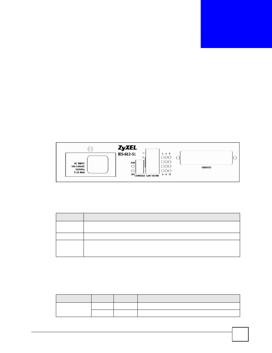
The figure below shows the front panel of the IES-612-51A.
Figure 6 Front Panel: AC Input
3.1.1 Front Panel Ports
The following table describes the port labels on the front panel.
3.2 LEDs
The following table describes the LEDs on the front panel.
Table 1 Front Panel Ports
LABEL
DESCRIPTION
CONSOLE
Only connect to this port if you want to configure the IES-612-51A using the command
line interface (CLI) via the console port.
LAN 10/100
Connect these ports to a computer, a hub, an Ethernet switch or router.
USER/CO
Connect the Telco-50 connector USER pins (14-25, 39-50) to subscribers respectively.
Connect the Telco-50 connector CO pins (1-12, 26-37) to the telephone company for
subscribers respectively.
Table 2 LEDs
LED
COLOR
STATUS
DESCRIPTION
ALM
Red
On
The IES-612-51A is functioning abnormally.
Off
The IES-612-51A is functioning normally.