ZyXEL Communications IES-612-51A User Manual
Page 126
Chapter 14 xDSL Profiles Setup
IES-612-51A User’s Guide
126
IGMP Filter Profile
Click IGMP Filter Profile to open the IGMP Filter Profile screen where you can
configure IGMP multicast filter profiles (see
Index
This is the port profile index number.
Name
These are the names of individual profiles. The DEFVAL profile always exists
and all of the DSL ports have it assigned to them by default. You can use up to
31 ASCII characters; spaces are not allowed.
Latency Mode
This is the ADSL latency mode (Fast or Interleave) for the ports that belong to
this profile.
Down/Up Stream
Rate (kbps)
These are the maximum downstream and upstream transfer rates for the ports
that belong to this profile.
Select
Modify
Select a profile’s Select radio button and click Modify to edit the profile.
Select
Delete
Select a profile’s Select radio button and click Delete to remove the profile.
The rest of the screen is for profile configuration.
Name
When editing a profile, this is the name of this profile. When adding a profile,
type a name (up to 31 characters) for the profile.
Latency Mode
This field sets the ADSL latency mode for the ports that belong to this profile.
Select Fast mode to use no interleaving and have faster transmission (a “fast
channel”). This would be suitable if you have a good line where little error
correction is necessary.
Select Interleave mode to use interleave delay when transmission error
correction (Reed- Solomon) is necessary due to a less than ideal telephone line.
See
for more on interleave delay.
Up Stream
The following parameters relate to upstream transmissions.
Max Rate
Type a maximum upstream transfer rate (64 to 4096 Kbps) for this profile.
Configure the maximum upstream transfer rate to be less than the maximum
downstream transfer rate.
Min Rate
Type the minimum upstream transfer rate (32 to 4096 Kbps) for this port.
Configure the minimum upstream transfer rate to be less than the maximum
upstream transfer rate.
Interleave Delay
Configure this field when you set the Latency Mode field to Interleave. Type
the number of milliseconds (1-255) of interleave delay to use for upstream
transfers. It is recommended that you configure the same latency delay for both
upstream and downstream.
Max SNR
Type the maximum upstream signal to noise margin (0-31 dB).
Min SNR
Type the minimum upstream signal to noise margin (0-31 dB). Configure the
minimum upstream signal to noise margin to be less than or equal to the
maximum upstream signal to noise margin.
Target SNR
Type the target upstream signal to noise margin (0-31 dB). Configure the target
upstream signal to noise margin to be greater than or equal to the minimum
upstream signal to noise margin and less than or equal to the maximum
upstream signal to noise margin.
Up Shift SNR
The upstream up shift signal to noise margin (0-31 dB). When the channel’s
signal to noise margin goes above this number, the device can attempt to use a
higher transfer rate. Configure the upstream up shift signal to noise margin to be
greater than or equal to the target upstream signal to noise margin and less than
or equal to the maximum upstream signal to noise margin.
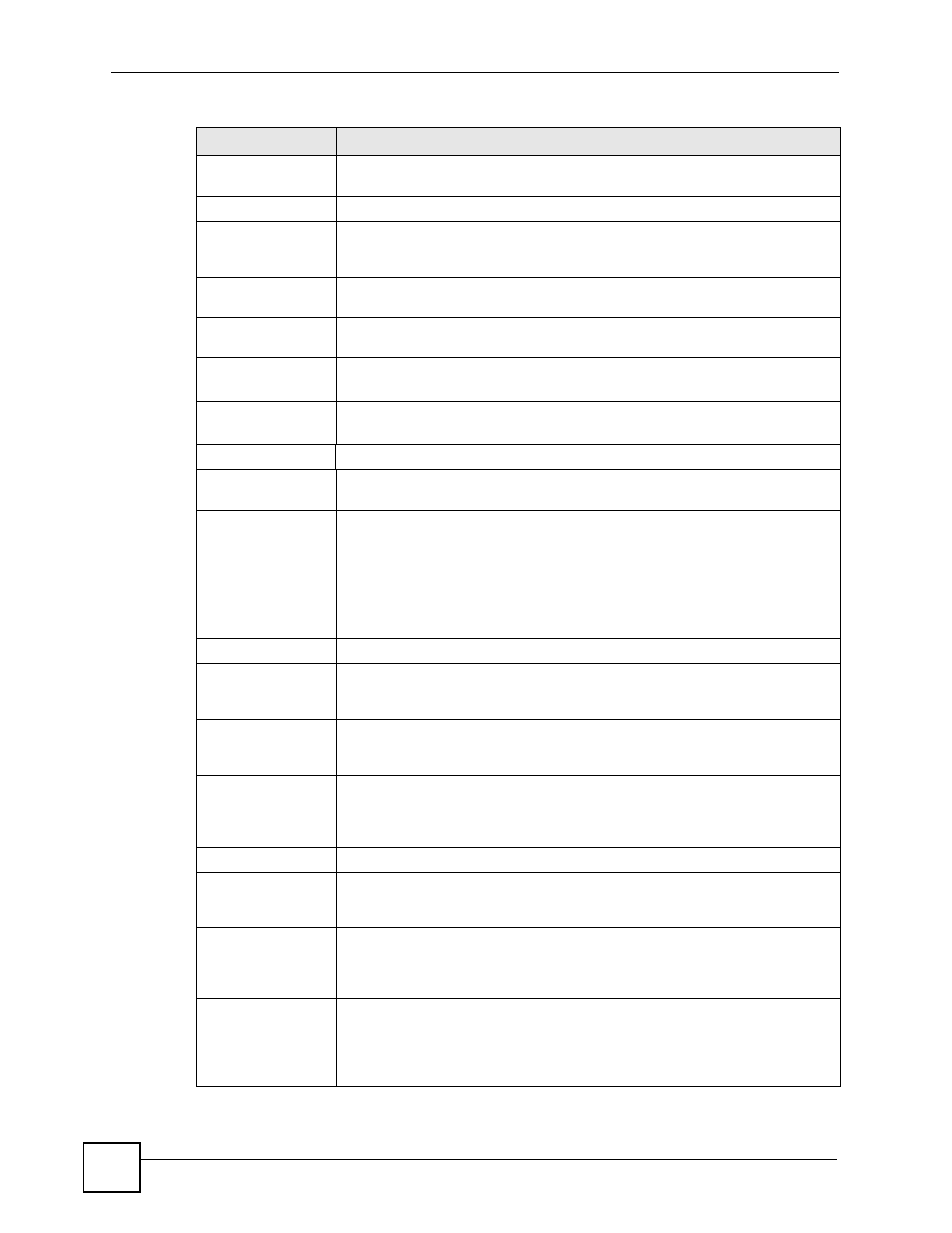
Table 25 Port Profile (continued)
LABEL
DESCRIPTION