Oki B4100 User Manual
Page 487
40055101TH Rev.4
487 /
A3.9 NTIF (NCU and TEL interface) Circuit Diagram (option)
NTIF board is used as an interface board of NCU, TEL and HOOK board. (Expect US version)
The relationship between NTIF and the peripheral block diagram is shown in A3.11 OKIFAX 4100/5000
series facsimile transceiver (page A3-101).
1.
Block diagram
NTIF board circuit consists of the following blocks:
1)
Dialing
The selection between the MF dial and the dial pulse (DP) is performed by SW2 setting.
SW4-3 should be set to ON, and SW4-4 set to OFF on TEL-W1.
2)
Route selection
The shunt wire activation for the UK version and the cascade connection of the external
TEL are performed by the ON/OFF settings of SW3-1,2 and 3. The Dip-switch settings are
shown below.
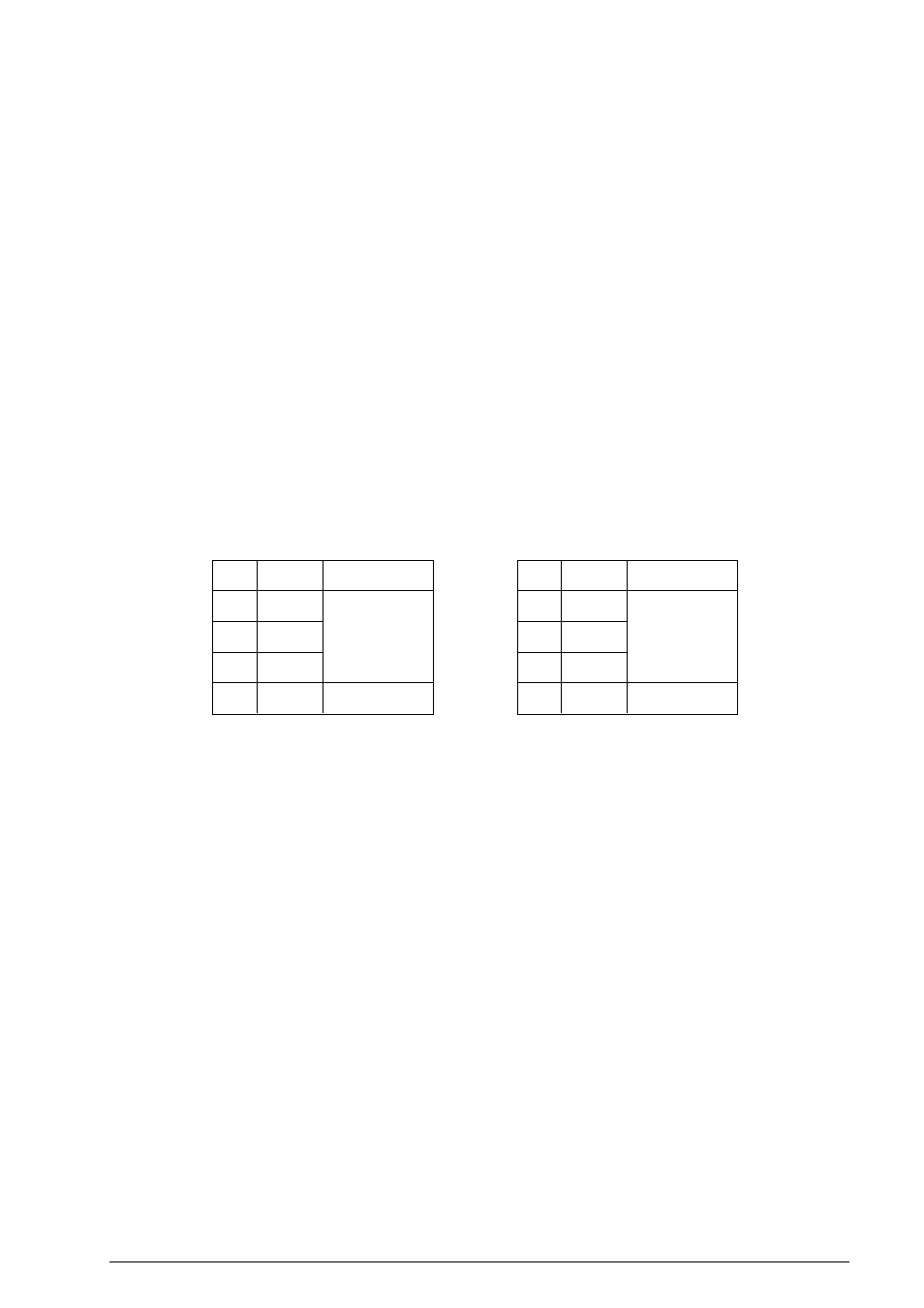
Each country’s hardware parameters comparison table:
No.
1
2
3
4
Setting
Dip-sw 3 Setting Table (U.K.)
OFF
ON
OFF
OFF
Remarks
Route change
Not used
No.
1
2
3
4
Setting
Dip-sw 3 Setting Table (Except U.K.)
ON
OFF
ON
OFF
Remarks
Route change
Not used
3)
Ringer circuit (for ABB/ABX type)
This circuit is used for the buzzer sound when optional telephone set is mounted on the
facsimile transceiver.
4)
Ring impedance
The circuit section related to the ring impedance is formed by C1, R4. R5, and R6.