Oki B4100 User Manual
Page 396
40055101TH Rev.4
396 /
1.
Block diagram
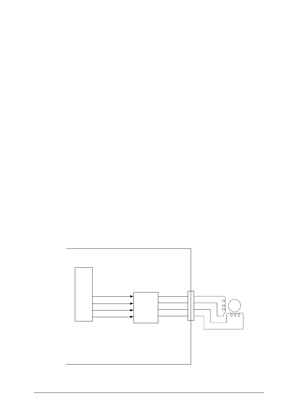
The circuit diagram shown on page 10/12 consists of the following function and connectors:
•
TA1 (Send motor driver)
•
Connector CN1 that provides an interface between R44 board and the send motor.
Figure A3.1.12 shows the related signals of the send motor and fan motor.
2.
Function
1)
Send motor rotation and chopper control
Send motor drive signals are generated by the IOGA3 and output to send motor via TA1
(motor drive IC) of this circuit.
Note: The built-in motor control circuit of IOGA3 consists of the following blocks:
•
Setting of the excitation operation
•
Setting of the chopping operation
•
Setting of the motor excitating method (1-2/2-1 phase excitation)
a)
Send motor rotation control
There are several cases of the rotation operation:
Forward rotation for feeding documents.
•
Case 1: Feeding document from hopper to the position where one line data is
read.
•
Case 2: Feeding document while reading.
•
Case 3: Feeding document after a page has been read.
b)
Send motor chopper control
The purpose of chopper control is to reduce the current to the motor by setting the
phase signal on and off intermittently when a time lapse exceeding a specific time
occurs without a phase update.
A3.1.11 R44 Circuit Diagram (Page 11/12)
Send motor
M
CN1
1
2
3
4
Send motor
drive
R44
(1-2 phase excitation)
TAI
IOGA
IC2
SPH1
SPH2
SPH3
SPH4
PHS1
PHS2
PHS3
PHS4
Figure A3.1.12 Related Signals of Send Motor