Pulse Modulation
Figure
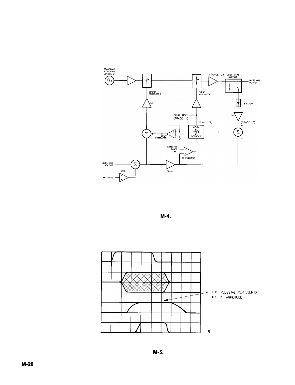
ALC Block Diagram
(B) PULSE WAVEFORMS
0
1 PULSE INPUT
2 RF
3 LOG AMP OUTPUT
S / H C O N T R O L
Pulse Modulation System
Operating and Programming Reference
HP 8360
User’s Handbook