Clear point, Connectors, Bnc connectors – HP 8360 User Manual
Page 176
Clear Point
Function Group
POWER
Menu Map
Description
This
lets you change the correction value for the active
frequency point to the “Undefined” state.
Programming Codes
SCPI:
NONE, see Fltness Menu
Analyzer:
NONE
S e e A l s o
Menu
“Optimizing Synthesizer Performance” in Chapter 1.
CONNECTORS
BNC Connectors
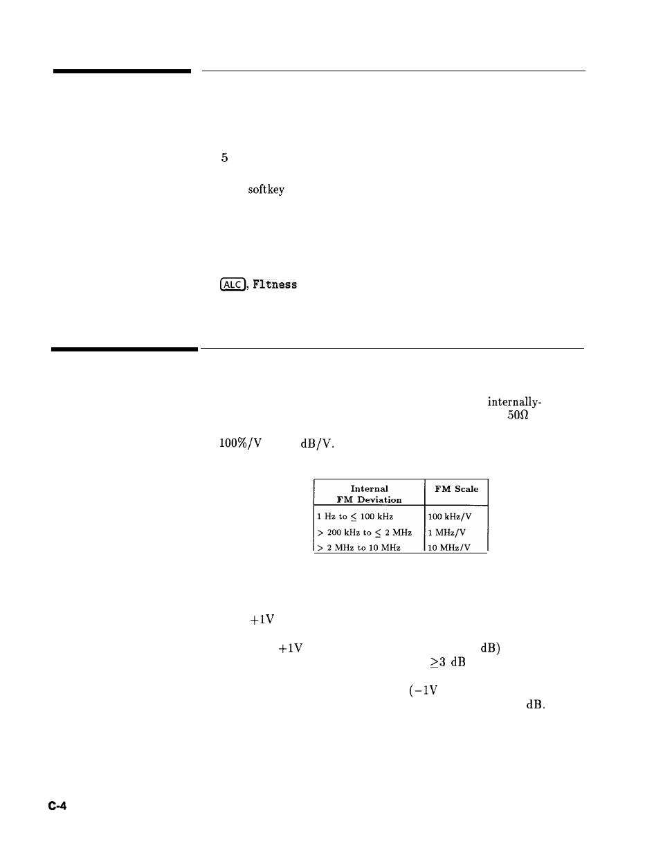
AM/FM OUTPUT
(Opt ion 002 only) Outputs the
generated AM or FM waveform. This output can drive
or
greater. The AM output is scaled the same as it is generated, either
or 10
The FM scaling depends on the FM deviation
chosen. The following table shows the scale versus deviation.
AM INPUT
There are two AM operation modes: linear and log.
When the synthesizer is in linear AM mode, the input accepts a
-1 to
signal. With an AM input of OV, the RF output level
(the reference level) is unaffected; at -lV input, the RF is shut off,
and with a
input, the RF output is 100% (3
higher that the
reference level. Therefore, there must be
of margin between
the reference power level and the maximum available at a given
frequency. The on (OV input) to off
input) ratio is a function
of power level and frequency, but is always greater than 20
The amplitude of the RF output changes linearly as the AM input
changes.
When the synthesizer is in log AM mode, the input accepts a wider
range of input signal. For every -lV input, the RF output level
Operating and Programming Reference HP 8360
User’s Handbook