Power supply – Gasboy CFN Series Diagnostic Manual User Manual
Page 91
Site Controller II
2210
3-27
Setting Floppy Disk Drives For Use With The Site Controller II
To prepare the disk drive, you must ensure that the select switches SW3 and SW1 are set
properly. These are located on the floppy drive’s PC board and may be accessed through two
small entry holes in the sheet metal shroud. NOTE: The switches are labeled, although they are
rather difficult to identify as they are printed on the PC board next to each switch. The switches
should be set as follows;
SW1
Set switch to position RY
SW3 (Drive select switch)
For the A drive, set switch to position D0
For the B drive, set switch to position D1
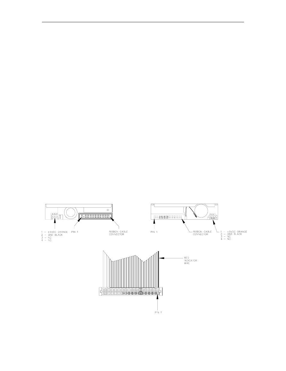
Installation
After setting the switches, you are ready to install your drive. The power supply cable connects to
a four-pin connector on the back end of the drive. The ribbon cable connects to the 34-pin
connector on the back end of the drive. Be sure to align Pin 1 of the cable with Pin 1 of the disk
drive connector. Due to the frequently changing nature of electronic components, the drive you
have may differ slightly from the one pictured below. However, Pin 1 is always the lower left-hand
pin on the connector, and Pin 1 on the connector is aligned with the wire of a different color
(usually red).
Be sure to connect your cable in the correct orientation. Failure to do so will cause the
loss of data.
POWER SUPPLY
The power supply provides the internal power used by the site controller. This unit: