Gasboy CFN Series Diagnostic Manual User Manual
Page 354
Site Controller III
12-20
1116
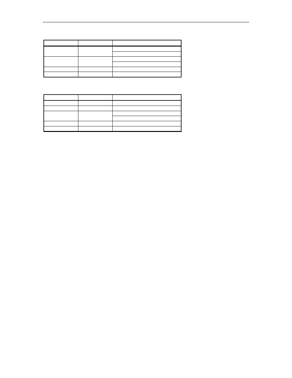
Switch S2
Switch
Function
Setting
Open – Disabled
S2-1
Battery 1
Closed – Enabled; default
Open – Disabled; default
S2-2
Battery 2
Closed – Enabled
S2-3
N/A
Unused
S2-4
N/A
Unused
Test Points - Memory PCB
Test Point
Function
Voltage
TP1
Ground
0 VDC
TP2
+5
+4.9 to +5.1 VDC
4.95 to 5.1 VDC with power on
TP3
Battery
3.0 to 3.3 VDC with power off
TP4
Battery 1
3.0 to 3.3 VDC
TP5
Battery 2
3.0 to 3.3 VDC
DC Power Measurements
1.
Remove the Phillips screws from the side access panel or cover of the PC. Carefully remove
the access panel or cover.
2.
To measure the +5V, on the CPU PCB, measure at the TP1 and TP2 test points, with the
positive (+) probe on TP2 and the negative (-) probe on TP1. The voltage should be +5.00 to
+5.15 VDC. No adjustment is possible.
3.
To measure the +12V, on the CPU PCB, measure at the TP1 and TP3 test points, with the
positive (+) probe on TP3 and the negative (-) probe on TP1. The voltage should be +11.00
to +14.00 VDC. No adjustment is possible.
4.
To measure the -12V, on the CPU PCB, measure at the TP1 and TP4 test points, with the
positive (+) probe on TP4 and the negative (-) probe on TP1. The voltage should be -11.00
to -14.00 VDC. No adjustment is possible.
NOTE: These voltages can not be adjusted.