Diagnostic tests, Start diagnostic mode, End diagnostic mode – Gasboy CFN Series Diagnostic Manual User Manual
Page 219

Pump Control Unit
12/26/02
6-29
DIAGNOSTIC TESTS
The pump control unit can perform a number of diagnostic tests on each pump connected to the
unit. These tests will check the operation of the pump and pump control unit. Tests can be
performed totally independent of the site controller.
CAUTION
AC power is present on some of the terminal blocks in this unit. Electrical shock may
occur if the operator comes in contact with these connections.
Start Diagnostic Mode
1.
Unlock, unscrew, and open the door of the pump control unit.
2.
Unscrew the large screw on the right hand side of the card cage. Pivot the cage away from
the chassis so that you can gain access to the CPU PCB.
3.
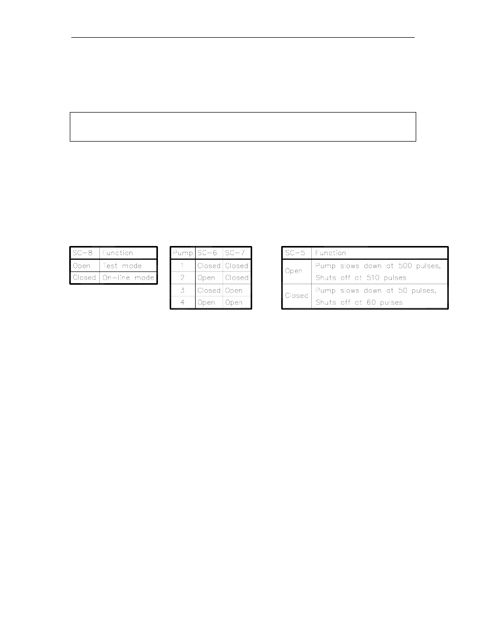
Open switch SC-8 (test mode switch). Set switches SC-5 (pump limit) and SC-6 and SC-7
(pump to test) to the desired settings.
SC-8 Test Mode
SC-6 & 7 Pump to Test
SC-5 Pump Limit
Diagnostic Tests
4.
Press and release the SA reset switch. The appropriate pump LED(s) should turn on and the
selected pump should be ready for activation.
5.
Turn on the pump handle. The pump should reset and the appropriate switch detect LED on
the I/O PCB should turn on.
6.
Begin to dispense product, the appropriate LED on the I/O PCB should pulse. The fast flow
LED will turn off at the preset slow down limit.
7.
Turn off the pump. The switch detect LED and all pump LED's should turn off. The pump
should not be able to be turned on again without pushing the reset switch.
End Diagnostic Mode
8.
Set the SC-6 to the open position (deadman timer enabled). Set the SC-8 switch to the
closed position (on-line mode).
9.
Press and release the SA reset switch. The PCU should be back in the on-line mode.
10. Swing the card cage back to the chassis and tighten the card cage screw.
11. Close and lock the PCU door. Tighten the two screws.
