Gasboy CFN Series Diagnostic Manual User Manual
Page 398

CFN Islander
13-30
12/26/02
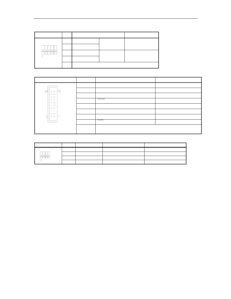
P5 Local port (or port 1) & P6 Remote port (or port 3) RS-422 Connections
Pinout
Pin
Function
Voltage
1
RS-422 Tx+
2
RS-422 Tx-
From
Islander
+5 VDC signal
between pins 1 & 2
3
RS-422 Rx+
4
RS-422 Rx-
To
Islander
+5 VDC signal
between pins 3 & 4
5
Ground
P7 Local port (or port 1) & P8 Remote port (or port 3) Internal modem Connections
Pinout
Pin
Function
Voltage
1
RXD – Receive Data
receive; +5 VDC OFF
4
-12 VDC
-12 VDC
5,14,19
+5 VDC
+5 VDC
7
DTR – Data terminal ready
0 VDC ON
10,18,20
DC Ground
DC Ground
13
+12 VDC
+12 VDC
15
TXD – Transmit Data
transmit; +5 VDC OFF
17
CD – Carrier detect
0 VDC ON
2,3,6,8,9
11,12,16
Not connected
P9 & P10 DC Power Input/Output
Pinout
Pin
Wire
Function
Voltage
1
White
-12 VDC
-12 VDC
2
Red
+12 VDC
+12 VDC
3
Black
DC Ground
DC Ground
4
Orange
+5 VDC
+5 VDC
Jumpers and Connections
Inside the Islander II, there are two Site Communication I/O boards. One connects Port 0
(referred to as LOCAL) and Port 2 (referred to as REMOTE) to the terminal blocks in the pedestal
or an internal modem. The other Site Communication I/O board connects Port 1 and Port 3 to the
terminal blocks or an internal modem. The connection from the Site Communication I/O board to
the terminal blocks in the pedestal must match method of communications used (RS-232 or RS-
422). The three 5-position and one 10-position connector cable assemblies are marked with the
terminal block number to which they connect in the pedestal. The default setting of the Islander is
RS-232 and the ports are as follows:
Port 0 to TB3 (5-position)
Port 2 to TB4 (10-position)
Port 1 to TB5 (5-position)
Port 3 to TB6 (5-position)
The brown wire from the cable connects to pin 1 of the connector. Pin 1 of the cable must align
with pin 1 of the board connector it is attached to. Use the illustration below to locate the jumpers
and use the chart on the following page to set the jumpers and to connect the terminal block
cables to the proper connectors on the board
