Gate controller wiring – Gasboy CFN Series Diagnostic Manual User Manual
Page 125
Island Card Reader
03/19/04
4-9
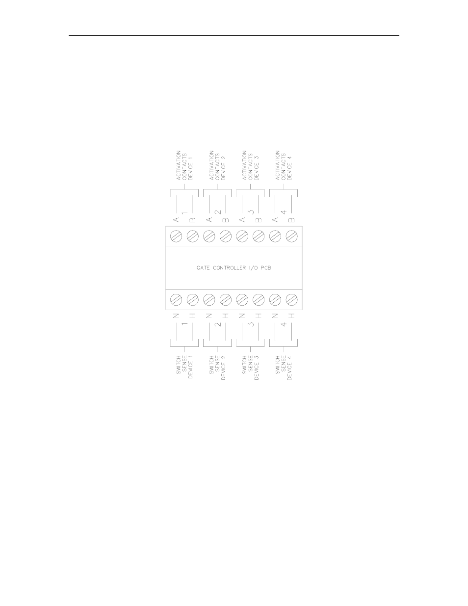
Gate Controller Wiring
Field wiring for devices connnected to the gate controller is accomplished via connectors on the
Gate Controller I/O PCB mounted in the ICR. Each gate controller can operate up to four devices
through one of four relays on the PCB. Each relay can handle up to 5 Amps at 30 VDC or 115
VAC. A 115 VAC switch sense signal can be used to turn the relay off, or it can turn off based on
the timeout period configured in the site controller. As with all CFN equipment , AC and DC
wiring must not run in the same conduit or wire trough.
See also other documents in the category Gasboy Hardware:
- 216S (18 pages)
- Atlas Fuel Systems Site Prep Manual (42 pages)
- Atlas Technician Programming Quick Ref (2 pages)
- ATC M05819K00X Kits (28 pages)
- Atlas Fuel Systems Owner Manual (80 pages)
- Gilbarco Global Pumping Unit Operation Manual (42 pages)
- 26 (7 pages)
- Atlas Valve Replacement Kits (10 pages)
- Atlas Fuel Systems Installation Manual (100 pages)
- 9120K (8 pages)
- 9820K (6 pages)
- Atlas Single Std. Inlet Centering Kit (8 pages)
- 8800 Atlas (1 page)
- 9120K Series Service Manual (40 pages)
- 9800A Atlas (6 pages)
- 9800 Atlas (14 pages)
- 9800 Atlas (20 pages)
- M08400 (6 pages)
- 9100 Series (8 pages)
- 9820K Series Installation (62 pages)
- 9853K (8 pages)
- 9216KTW (36 pages)
- Recommended Spare Atlas (14 pages)
- DEF Atlas (28 pages)
- 9820K Series (12 pages)
- 9800Q (1 page)
- Q Series (3 pages)
- 8753E (2 pages)
- 9152AXTW2 (1 page)
- 8800E (2 pages)
- 8800E (1 page)
- 9820Q Series (1 page)
- Atlas Start-up (230 pages)
- 2600A (12 pages)
- 2600A (2 pages)
- 9800Q Front Load Vapor (2 pages)
- 215A (1 page)
- 9800A (4 pages)
- 9820A (1 page)
- 2600A (3 pages)
- 216A (31 pages)
- 215A (2 pages)
- 9800Q Vapor (2 pages)
- Lamp Kit (2 pages)
- 9120Q Pulser (1 page)