Gasboy CFN Series Diagnostic Manual User Manual
Page 345
Site Controller III
1116
12-11
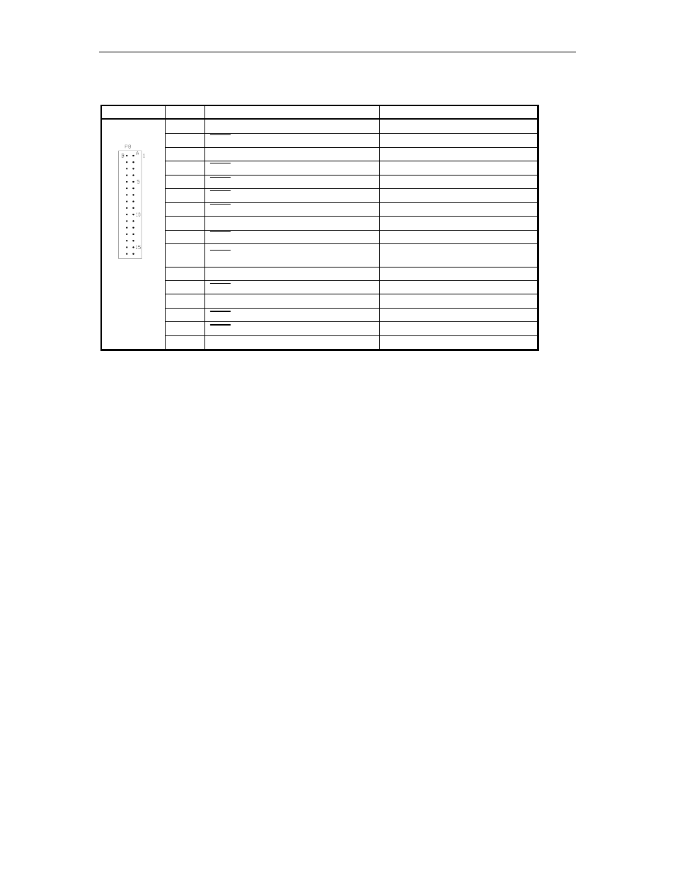
P8 - Memory PCB Communication ports Interface (Continued)
Pins B1 - B16
Pinout
Pin
Function
Voltage
B1
RXD – Receive data, port 4
receive; +5VDC OFF
B2
DSR – Data set ready, port 4
0VDC – ON
B3
TXD – Transmit data, port 4
transmit; +5VDC OFF
B4
CTS – Clear to send, port 4
0VDC – ON
B5
DCD – Carrier detect, port 4
0VDC – ON
B6
RTS – Ready to send, port 4
0VDC – ON
B7
DTR – Data terminal ready, port 4
0VDC – ON
B8
DC Ground
DC Ground
B9
DTR – Data terminal ready, port 3
Not used +5VDC
B10
RTS – Ready to send, port 3
0VDC Tokheim Channel 1;
+5VDC Tokheim Channel 2
B11
TXD – Transmit data, port 3
transmit; +5VDC OFF
B12
DSR – Data set ready, port 3
Not used 0VDC
B13
RXD – Receive data, port 3
receive; +5VDC OFF
B14
DCD – Carrier detect, port 3
Not used 0VDC
B15
CTS – Clear to send, port 3
Not used 0VDC
B16
+12VDC
+12VDC
- 216S (18 pages)
- Atlas Fuel Systems Site Prep Manual (42 pages)
- Atlas Technician Programming Quick Ref (2 pages)
- ATC M05819K00X Kits (28 pages)
- Atlas Fuel Systems Owner Manual (80 pages)
- Gilbarco Global Pumping Unit Operation Manual (42 pages)
- 26 (7 pages)
- Atlas Valve Replacement Kits (10 pages)
- Atlas Fuel Systems Installation Manual (100 pages)
- 9120K (8 pages)
- 9820K (6 pages)
- Atlas Single Std. Inlet Centering Kit (8 pages)
- 8800 Atlas (1 page)
- 9120K Series Service Manual (40 pages)
- 9800A Atlas (6 pages)
- 9800 Atlas (20 pages)
- 9800 Atlas (14 pages)
- M08400 (6 pages)
- 9100 Series (8 pages)
- 9820K Series Installation (62 pages)
- 9853K (8 pages)
- 9216KTW (36 pages)
- Recommended Spare Atlas (14 pages)
- DEF Atlas (28 pages)
- 9820K Series (12 pages)
- 9800Q (1 page)
- Q Series (3 pages)
- 8753E (2 pages)
- 9152AXTW2 (1 page)
- 8800E (2 pages)
- 8800E (1 page)
- 9820Q Series (1 page)
- Atlas Start-up (230 pages)
- 215A (1 page)
- 9800A (4 pages)
- 9820A (1 page)
- 2600A (3 pages)
- 2600A (12 pages)
- 2600A (2 pages)
- 9800Q Front Load Vapor (2 pages)
- 9800Q Vapor (2 pages)
- 216A (31 pages)
- 215A (2 pages)
- Lamp Kit (2 pages)
- 9120Q Pulser (1 page)