P1 - memory pcb interface – Gasboy CFN Series Diagnostic Manual User Manual
Page 341
Site Controller III
1116
12-7
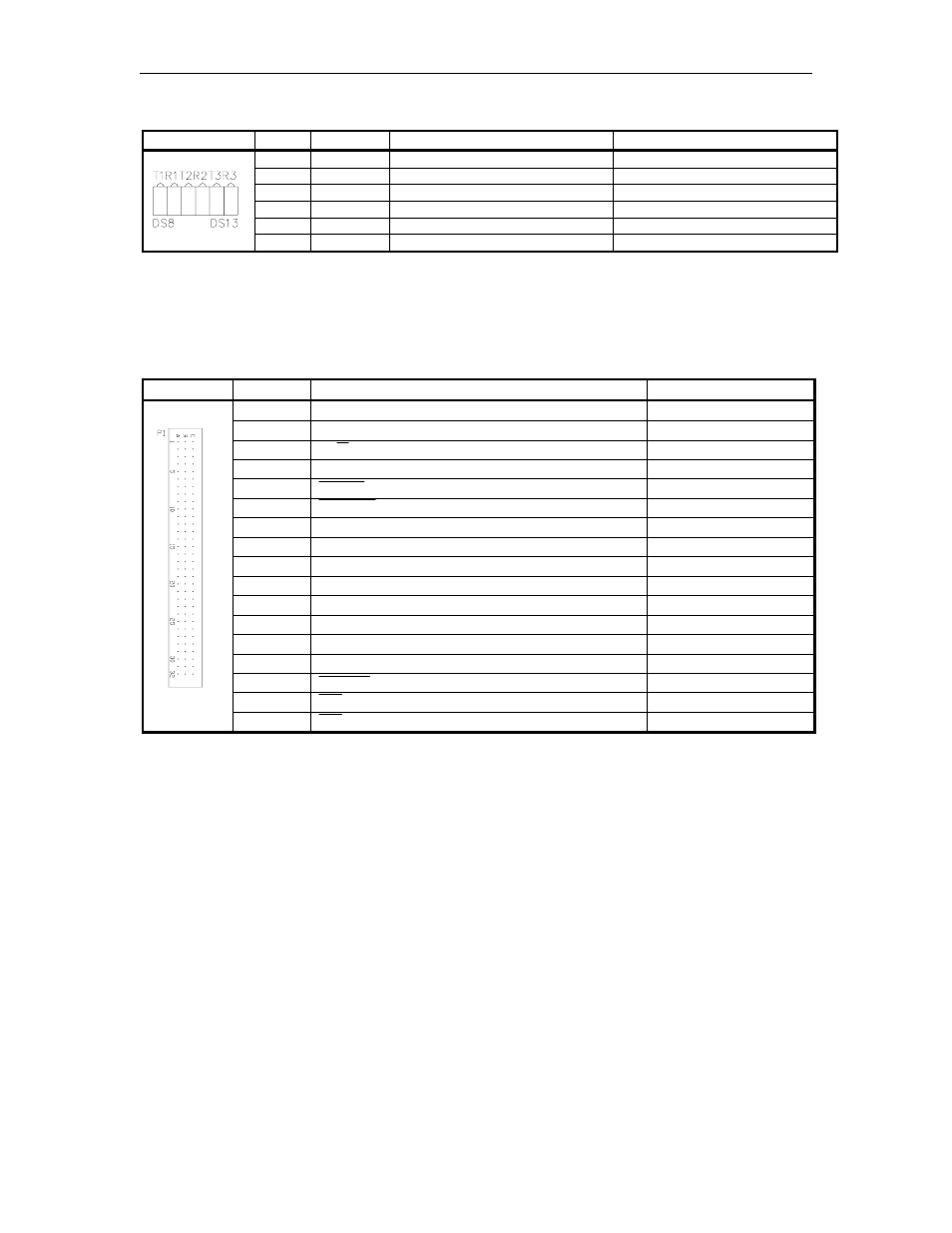
485 Loop Communications LEDs
LED
Color
Function
Status
DS8
Green
Transmit on RS-485 loop 3
Flashes during communications
DS9
Red
Receive on RS-485 loop 3
Flashes during communications
DS10
Green
Transmit on RS-485 loop 2
Flashes during communications
DS11
Red
Receive on RS-485 loop 2
Flashes during communications
DS12
Green
Transmit on RS-485 loop 1
Flashes during communications
DS13
Red
Receive on RS-485 loop 1
Flashes during communications
Connectors
P1 - Memory PCB Interface
Pins A1- A32
Pinout
Pin
Function
Voltage
A1
+5VDC
+5VDC
A2
+5VDC
+5VDC
A3
W/R – Read Enable
0VDC – Read
A4
PB9
+5VDC – ON
A5
MBSEL – Memory Board Select
0VDC – ON
A6
BUSSEL – Not used, grounded on Memory PCB
0VDC – Normal
A7
N/C
A8
N/C
A9
N/C
A10–A25
GND – DC Ground
DC Ground
A26
N/C
N/C
A27
N/C
N/C
A28
IPL0
+5VDC – ON
A29
IPL1
+5VDC – ON
A30
BGACK
0VDC – ON
A31
BG
0VDC – ON
A32
BR
0VDC – ON
- 216S (18 pages)
- Atlas Fuel Systems Site Prep Manual (42 pages)
- Atlas Technician Programming Quick Ref (2 pages)
- ATC M05819K00X Kits (28 pages)
- Atlas Fuel Systems Owner Manual (80 pages)
- Gilbarco Global Pumping Unit Operation Manual (42 pages)
- 26 (7 pages)
- Atlas Valve Replacement Kits (10 pages)
- Atlas Fuel Systems Installation Manual (100 pages)
- 9820K (6 pages)
- 9120K (8 pages)
- Atlas Single Std. Inlet Centering Kit (8 pages)
- 8800 Atlas (1 page)
- 9120K Series Service Manual (40 pages)
- 9800A Atlas (6 pages)
- 9800 Atlas (20 pages)
- 9800 Atlas (14 pages)
- M08400 (6 pages)
- 9100 Series (8 pages)
- 9820K Series Installation (62 pages)
- 9853K (8 pages)
- 9216KTW (36 pages)
- Recommended Spare Atlas (14 pages)
- DEF Atlas (28 pages)
- 9820K Series (12 pages)
- 9800Q (1 page)
- Q Series (3 pages)
- 8753E (2 pages)
- 9152AXTW2 (1 page)
- 8800E (2 pages)
- 8800E (1 page)
- 9820Q Series (1 page)
- Atlas Start-up (230 pages)
- 9800A (4 pages)
- 9820A (1 page)
- 2600A (3 pages)
- 2600A (12 pages)
- 2600A (2 pages)
- 9800Q Front Load Vapor (2 pages)
- 215A (1 page)
- 9800Q Vapor (2 pages)
- 216A (31 pages)
- 215A (2 pages)
- Lamp Kit (2 pages)
- 9120Q Pulser (1 page)