Gasboy CFN Series Diagnostic Manual User Manual
Page 397
CFN Islander
12/26/02
13-29
Connectors
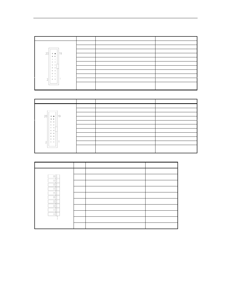
P1 Local port (or port 1 on Islander II) Interface
Pinout
Pin
Function
Input/Output
3
TxD – Transmit data
Output to SC CPU
4
RxC – Receive clock, synchronous
Not used
5
RxD – Receive data
Input from SC CPU
7
RTS – Request to send
Output to SC CPU
8
TxC – Transmit clock, synchronous
Not used
9
CTS – Clear to send
Input from SC CPU
11
DTR – Data terminal ready
Input from SC CPU
13
Signal ground
Ground
14
CD – Carrier Detect
Output to SC CPU
15
DSR – Data set ready
Output to SC CPU
1,2,6,10,
12,16-20
Not connected
Not connected
P2 Remote port (or port 3 on Islander II) Interface
Pinout
Pin
Function
Input/Output
3
RxD – Receive data
Input from SC CPU
4
TxC – Transmit clock, synchronous
Not used
5
TxD – Transmit data
Output to SC CPU
7
CTS – Clear to send
Input from SC CPU
8
RxC – Receive clock, synchronous
Not used
9
RTS – Request to send
Output to SC CPU
11
DSR – Data set ready
Output to SC CPU
13
Signal ground
Ground
14
DTR – Data terminal ready
Input from SC CPU
15
CD – Carrier Detect
Output to SC CPU
1,2,6,10,
12,16-20
Not connected
Not connected
P3 Local port (or port1) & P4 Remote port (or port 3) RS-232 Connections
Pinout
Pin
Function
Input/Output
1
TxD – Transmit data
Output
2
DTR – Data terminal ready
Output
3
RxD – Receive data
Input
4
CTS – Clear to send
Input
5
Signal ground
Ground
6
RTS – Request to send
Output
7
CD – Carrier Detect
Input
8
DSR – Data set ready
Input
9
TxC – Transmit clock, synchronous
Not used
10
RxC – Receive clock, synchronous
Not used