Gasboy CFN Series Diagnostic Manual User Manual
Page 271
CFN System
1310
7-35
DC Power Measurements and Adjustment for C05423 Power Supply
+5 VDC Measurement
1.
Turn off power to the console. Remove the four screws from the bottom of the console and
carefully separate the upper housing from the lower housing.
2.
Turn on the power to the console.
CAUTION
AC voltage will be present in the power supply area. Be careful not to touch the supply or
AC input components.
3.
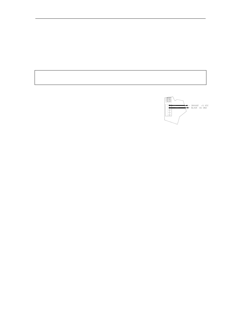
On the rear of the CPU PCB, measure the +5 VDC between
the orange (+) and black (-) wires on P2. The voltage
should be between +5.00 and +5.10. If the voltage does not
fall within this range, adjustment will be necessary. Follow
the steps below to adjust the supply. If the voltage is in
tolerance, skip to Step 7.
+5 VDC Adjustment
4.
Attach the meter probes to P2 on the CPU PCB.
5.
Using a 1/8 inch or smaller plastic, flat-blade screwdriver, adjust the power supply to +5 VDC
by turning the screw clockwise to increases voltage, counterclockwise to decrease voltage.
Turn the screw slightly to judge how sensitive the adjustment is.
6.
Disconnect the meter probes.
+12 VDC Measurement
7.
On the power supply, measure the +12 VDC between the red (+VDC post) and the black
(+VDC COM post) wires. The voltage should be 11.00 to +14.00.
NOTE: This voltage is used only for the cash drawer and is not adjustable.
8.
Turn off power to the console and carefully set the upper half of the console on the lower
half. Replace the four screws in the bottom of the unit. Turn on the power.