Ac power switch, Battery switch, Fuses – Gasboy CFN Series Diagnostic Manual User Manual
Page 213: Ac power fuse, F1 - +12 vdc fuse, F2 - +5 vdc fuse, 5 vdc, Measurement
Pump Control Unit
12/26/02
6-23
Switches
AC Power Switch
This switch turns on/off the AC power to the power supply. DC voltage will continue to be present
in the PCU for about 10 seconds after this switch is turned off because of the battery backup
feature.
Battery Switch
This switch enables the battery backup power in case of a power failure and also enables the
battery charge. The battery power will keep the PCU running for approximately 10 seconds (long
enough for all pumps to shut down). This switch should be ON for normal operation and OFF
whenever parts are replaced in the PCU.
Fuses
AC Power Fuse
An AC power fuse protects the input to the power supply. This fuse is rated at 1 Amp, slow blow.
F1 - +12 VDC Fuse
A pico fuse is located at position F1 on the power supply PCB. This fuse protects the power
supply from surges on the +12 VDC line. The fuse is rated at 1.5 Amps.
F2 - +5 VDC Fuse
A pico fuse is located at position F2 on the power supply PCB. This fuse protects the power
supply from surges on the +5 VDC line. The fuse is rated at 3 Amps.
+5 VDC
Measurement
1.
Turn off the AC and DC power switches on the supply assembly.
2.
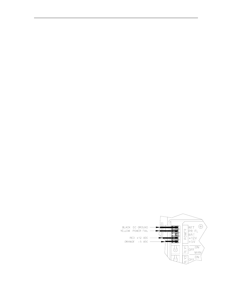
Locate the connector labeled POWER in the upper left-hand corner of the motherboard.
Remove the black plastic cover.
3.
Turn on the AC and DC power switches.
4.
Measure the +5 VDC between the orange (+) and black (-) wires. The voltage should be
+4.95 to +5.05 VDC.
5.
Measure the +12 VDC between the red (+) and black (-) wires. The voltage should be
+11.50 to +15.50 VDC depending on the type and number of pulsers and the number of
relays energized.
6.
Measure the POWER FAIL between the
yellow (+) and black (-) wires. The
voltage should be +4.75 to +5.05 VDC.
NOTE: There are no adjustments for
these voltages.
7.
Turn off the AC and DC power switches.
8.
Replace the black plastic cover on the
connector and turn the AC and DC
power switches back on.