Led indicators, Connector – Gasboy CFN Series Diagnostic Manual User Manual
Page 200
GASBOY CFN Series
6-10
12/26/02
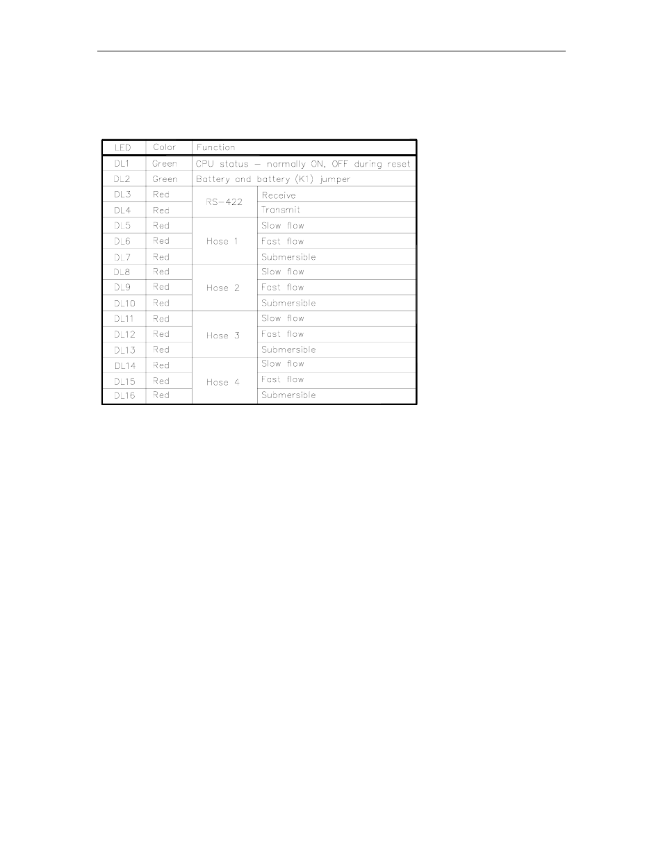
LED Indicators
LED indicators are provided to allow you to monitor the pump control unit's operation. These
LED's indicate the signal levels at the CPU PCB.
Connector
These notes apply to the chart P1 - Motherboard Interface Connector on the following page.
Note 1:
When using this board in a pump control unit with a pedestal pump control (PPC) I/O board, the
switch detect and reset complete signals are tied together on the I/O board. These signals will be
present on pins 2, 3, 4, and 5. Pins 6, 7, 8, and 9 will read +5VDC due to on-board pull-up
resistors.
Note 2:
When using this board in a pump control unit with a pedestal pump control (PPC) I/O board, the
AUX PULSER pins are grounded. When using this board with a PPC I/O Board II, the AUX
PULSER pins will be +5VDC with single pulsers and a +5VDC square wave signal during pumping
with dual pulsers.
Note 3:
The power supply battery monitor input warns the site controller of a battery-fail condition in the
pump control unit's power supply. The present pump control unit hardware does not support this
feature, therefore, +5VDC will be measured due to an on-board pull-up resistor.