P8 - memory pcb communication ports interface – Gasboy CFN Series Diagnostic Manual User Manual
Page 344
Site Controller III
12-10
1116
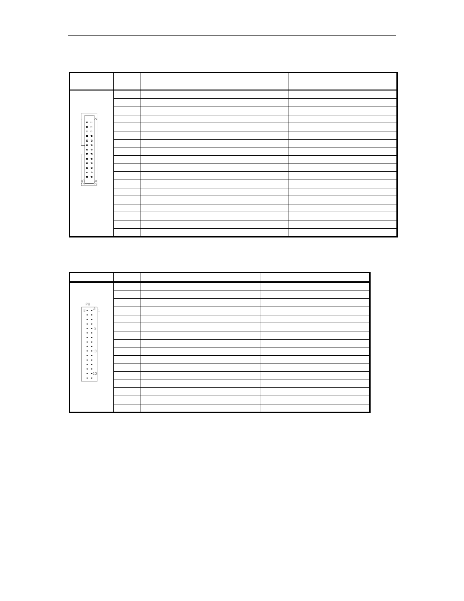
P7 – RS-232 General Purpose Synchronous Communications Port 2
Pinout
Pin
Function
Input/Output or
Determining Jumper
1
N/C
N/C
2
N/C
N/C
3
TXD – Transmit data
Output
4
TXC – Transmit clock synchronous
Input if K10 jumpered
5
RXD – Receive data
Input
6
N/C
N/C
7
RTS – Request to send
Output
8
RXC – Receive clock synchronous
Input if K8 jumpered
9
CTS – Clear to send
Input
10
N/C
N/C
11
DSR – Data set ready
Input
12
N/C
N/C
13
DC ground
DC ground
14
DTR – Data terminal ready
Output
15
DCD – Carrier detect
Input
16-21
N/C
N/C
22
ETXC – External serial clock, synchronous
Output if K9 jumpered
23-26
N/C
N/C
P8 - Memory PCB Communication ports Interface
Pins A1 - A16
Pinout
Pin
Function
Input/Output
A1
RXD – Receive data, port 6
Input
A2
TXD – Transmit data, port 6
Output
A3
DSR – Data set ready, port 6
Input
A4
DTR – Data terminal ready, port 6
Output
A5
CTS – Clear to send, port 6
Input
A6
RTS – Ready to send, port 6
Output
A7
DCD – Carrier detect, port 6
Input
A8
DC Ground
DC Ground
A9
DCD – Carrier detect, port 5
Input
A10
RTS – Ready to send, port 5
Output
A11
CTS – Clear to send, port 5
Input
A12
DTR – Data terminal ready, port 5
Output
A13
DSR – Data set ready, port 5
Input
A14
TXD – Transmit data, port 5
Output
A15
RXD – Receive data, port 5
Input
A16
-12VDC
-12VDC