Pc isa bus interface connector, P6 – dual tokheim port 3, Switch s1 – Gasboy CFN Series Diagnostic Manual User Manual
Page 353
Site Controller III
1116
12-19
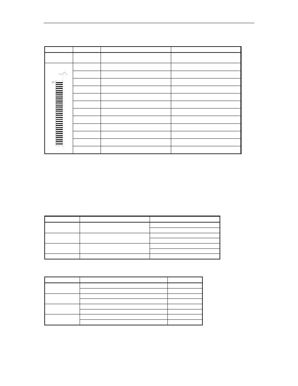
PC ISA Bus Interface connector
Pinout
Pin
Function
Voltage
Component
side
A1-A31
No connections
N/C
B1
Ground
Ground
B2
N/C
N/C
B3
+5 VDC
+5 VDC
B4-6
N/C
N/C
B7
-12 VDC
-12 VDC
B8
N/C
N/C
B9
+12 VDC
+12 VDC
B10
Ground
Ground
B11-28
N/C
N/C
B29
+5 VDC
+5 VDC
B30
N/C
N/C
Solder Side
B31
Ground
Ground
See the charts shown earlier in this section for the exact pinouts of these connectors.
P3, P4, & P5 - RS-232 General Purpose Communications Ports 6, 5, and 4 respectively
P6 – Dual Tokheim Port 3
LED Indicator DL2
LED indicator is provided to allow you to monitor the battery voltage. When lit, it indicates the
battery voltage is low or the battery is not connected.
Jumpers
Jumper
Description
Setting
1-2 for 4 wait state; default
K1
Date/Time clock speed
2-3 for 1 wait state
2-3 for 128Kx8; default
K2
Enable A19 to RAM
1-2 for 512Kx8
2-3 for 128Kx8; default
K3
RAM size
1-2 for 512Kx8
K5
Tokheim reset output
Not used.
Switches
Switch S1
Switch
Function
Setting
Boot to monitor after reset
Open
S1-1
Boot to OS after reset
Closed; default
Debug mode
Open
S1-2
Normal
Closed; default
Don’t talk to PC while in monitor
Open
S1-3
Monitor I/O goes to PC also
Closed; default
Monitor I/O goes to SC port 1 also
Open
S1-4
No monitor I/O to SC port 1
Closed; default