Gasboy CFN Series Diagnostic Manual User Manual
Page 380

CFN Islander
13-12
12/26/02
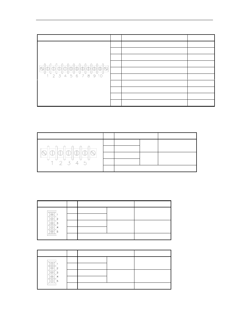
RS-232 - Modem Communications Remote Port – TB4
Pinout
Pin
Function
Input/Output
1
TxD – Transmit data
Output
2
DTR – Data terminal ready
Output
3
RxD – Receive data
Input
4
CTS – Clear to send
Input
5
Signal ground
Ground
6
RTS – Request to send
Output
7
CD – Carrier Detect
Input
8
DSR – Data set ready
Input
9
TxC – Transmit clock, synchronous
Not used
10
RxC – Receive clock, synchronous
Not used
All the RS-232 ports listed above can also be configured for RS-422 mode. The table below
shows the pinout and function for these ports in the RS-422 mode. Note: On the remote port
(TB4) in RS-422 mode, pins 6 – 10 are not connected.
Communication Port RS-422 Mode – TB3, TB4,TB5 or TB6
Pinout
Pin
Function
Voltage
1
RS-422 Tx+
2
RS-422 Tx-
From
Islander
+5 VDC signal
between pins 1 & 2
3
RS-422 Rx+
4
RS-422 Rx-
To
Islander
+5 VDC signal
between pins 3 & 4
5
Ground
The RS-485 communication to other CFN components (satellite readers, wall-mount PCUs, etc.)
comes through the upper RS-485 junction box board in the pedestal. Communication to the
console, if present, goes through the lower RS-485 junction box board in the pedestal.
RS-485 - Loop 1 Island Communications TB1 – Upper junction box board
Pinout
Pin
Function
Voltage
1
RS-485 Rx+
2
RS-485 Rx-
From
Island
+5 VDC signal
between pins 1 & 2
3
RS-485 Tx+
4
RS-485 Tx-
To
Island
+5 VDC signal
between pins 3 & 4
5
Ground
Ground
RS-485 - Loop 2 Console Communications TB1 – Lower junction box board
Pinout
Pin
Function
Voltage
1
RS-485 Rx+
2
RS-485 Rx-
From
Console
+5 VDC signal
between pins 1 & 2
3
RS-485 Tx+
4
RS-485 Tx-
To
Console
+5 VDC signal
between pins 3 & 4
5
Ground
Ground
