Pc isa bus interface connector – solder side, P9 - rs-232 general purpose communications port 1, P10 - rs-485 console communications loop 3 – Gasboy CFN Series Diagnostic Manual User Manual
Page 347

Site Controller III
1116
12-13
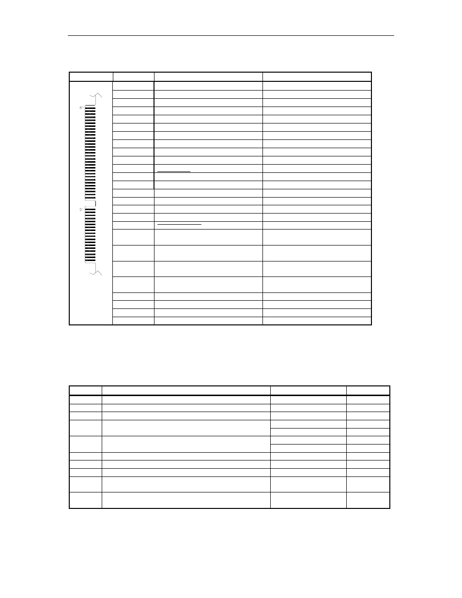
PC ISA Bus Interface connector – Solder Side
Sections B and D
Pinout
Pin
Function
Voltage
B1
GND – DC Ground
DC Ground
B2
N/C
N/C
B3
VCC - +5VDC
+5VDC
B4
N/C
N/C
B5
N/C
N/C
B6
N/C
N/C
B7
-12VDC
-12VDC
B8
N/C
N/C
B9
+12VDC
+12VDC
B10
GND – DC Ground
DC Ground
B11
PCMEMW – Dual RAM Write
0VDC-On
B12
PCMEMR – Dual RAM Read
0VDC-On
B13 to 28
N/C
N/C
B29
+5VDC
+5VDC
B30
N/C
N/C
B31
GND – DC Ground
DC Ground
D1
PCMEMCS16
0VDC – On
D2
N/C
N/C
D3
IRQ10 – Interrupt Request 10
S1-4 closed -
0VDC – On
S1-4 open – N/C
D4
IRQ11 – Interrupt Request 11
S1-3 closed -
0VDC – On
S1-3 open – N/C
D5
IRQ12 – Interrupt Request 12
S1-2 closed -
0VDC – On
S1-2 open – N/C
D6
IRQ15 – Interrupt Request 15
S1-1 closed -
0VDC – On
S1-1 open – N/C
D7 to D15
N/C
N/C
D16
+5VDC
+5VDC
D17
N/C
N/C
D18
GND – DC Ground
DC Ground
See the charts shown earlier in this section for the exact pinouts of these connectors:
P9 - RS-232 General Purpose Communications Port 1
P10 - RS-485 Console Communications Loop 3
P11 & P12 - RS-485 Island Communications Loops 1 & 2
Jumpers
Switch
Function
Setting
Default
K3
AC power fail sense
1, 2, & 3 Jumpered
Jumpered
K4
AC watchdog timer
1-2 to enable
Jumpered
K5
SC-Comm CPU (testing only)
1-2 to reset
Open
2-3 for 4-wire
Jumpered
K6
RS-485 loop 1, 2 to 4 wire
1-2 for 2-wire
Open
2-3 for 4-wire
Open
K7
RS-485 loop 2, 2 to 4 wire
1-2 for 2-wire
Jumpered
K8
Rx clock from synchronous modem (Port 2)
1-2 to connect
Open
K9
ETC output to synchronous modem (Port 2)
1-2 to connect
Open
K10
Tx clock input from synchronous modem (Port 2)
1-2 to connect
Open
K11
EPROM type
1-2 for 27512
2-3 for 27256/25128
Open
Jumpered
K12
EPROM type
1-2 for 27512
2-3 for 27256/25128
Open
Jumpered
