P2 - cpu pcb communication ports interface – Gasboy CFN Series Diagnostic Manual User Manual
Page 352
Site Controller III
12-18
1116
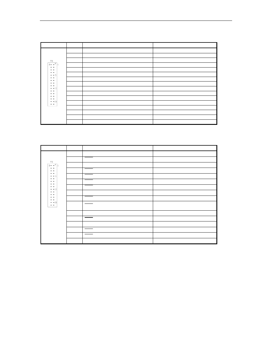
P2 - CPU PCB Communication ports Interface
Pins A1 - A16
Pinout
Pin
Function
Input/Output
A1
RXD – Receive data, port 6
Input
A2
TXD – Transmit data, port 6
Output
A3
DSR – Data set ready, port 6
Input
A4
DTR – Data terminal ready, port 6
Output
A5
CTS – Clear to send, port 6
Input
A6
RTS – Ready to send, port 6
Output
A7
DCD – Carrier detect, port 6
Input
A8
DC Ground
DC Ground
A9
DCD – Carrier detect, port 5
Input
A10
RTS – Ready to send, port 5
Output
A11
CTS – Clear to send, port 5
Input
A12
DTR – Data terminal ready, port 5
Output
A13
DSR – Data set ready, port 5
Input
A14
TXD – Transmit data, port 5
Output
A15
RXD – Receive data, port 5
Input
A16
-12VDC
-12VDC
P2 - CPU PCB Communication ports Interface (Continued)
Pins B1 - B16
Pinout
Pin
Function
Voltage
B1
RXD – Receive data, port 4
receive; +5VDC OFF
B2
DSR – Data set ready, port 4
0VDC – ON
B3
TXD – Transmit data, port 4
transmit; +5VDC OFF
B4
CTS – Clear to send, port 4
0VDC – ON
B5
DCD – Carrier detect, port 4
0VDC – ON
B6
RTS – Ready to send, port 4
0VDC – ON
B7
DTR – Data terminal ready, port 4
0VDC – ON
B8
DC Ground
DC Ground
B9
DTR – Data terminal ready, port 3
Not used +5VDC
B10
RTS – Ready to send, port 3
0VDC Tokheim Channel 1;
+5VDC Tokheim Channel 2
B11
TXD – Transmit data, port 3
transmit; +5VDC OFF
B12
DSR – Data set ready, port 3
Not used 0VDC
B13
RXD – Receive data, port 3
receive; +5VDC OFF
B14
DCD – Carrier detect, port 3
Not used 0VDC
B15
CTS – Clear to send, port 3
Not used 0VDC
B16
+12VDC
+12VDC