Gasboy CFN Series Diagnostic Manual User Manual
Page 395
CFN Islander
12/26/02
13-27
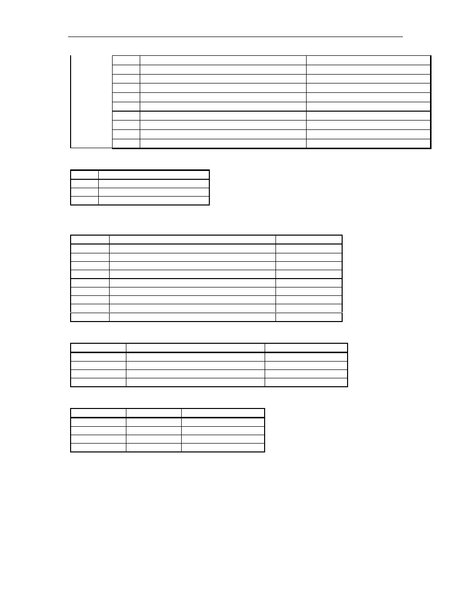
53
PA22 - Address line 22
+5 VDC - On
54
PA23 - Address line 23
+5 VDC - On
55
PA24 - Address line 24
+5 VDC - On
56
PA25 - Address line 25
+5 VDC - On
57-61
Not connected
NC - not used
62
BVD1 - PCMCIA Battery 1 Voltage
+5 VDC - PCMCIA Battery 1 OK
63
BVD2 - PCMCIA Battery 2 Voltage
+5 VDC - PCMCIA Battery 2 OK
64-66
Not connected
NC - not used
67
CD2 - Card Detect
0 VDC - On
68
DC Ground
DC ground
LED indicators
LED
Function
D3
Battery Function OK
D4
Battery Function Low
D5
Accessing PCMCIA Cards
Jumpers
Jumper
Function
Setting for SC 2
K1
SC1 / SC2 Selection
SC2
K2
PCMCIA IRQ Enable
Disable
K3
SC1 / SC2 Selection
SC2
K4
SC2 or SC1 – NO PCMCIA / SC1 - PCMCIA
SC2
K5
Memory Address line 14 Disable
open
K6
Memory Address line 13 Disable
open
K7
SC1 PCMCIA Enable
open
K8
PCMCIA Drive 3 IRQ Enable
open
K9
PCMCIA Drive 4 IRQ Enable
open
Switches
Switch
Function
Settings for SC 2
SW1-1
Enable battery 1
Closed
SW1-2
Enable battery 2
Open
SW1-3
Enable battery backup to CPU PCB
Open
SW1-4
SC1/SC2 Selection
Open for SC2
Test Points
Test Point
Function
Voltage
TP1
Battery-1
3.0 - 3.5 VDC
TP2
Battery-2
3.0 - 3.5 VDC
TP-3
Ground
0 VDC
TP-4
Vcc
4.90 - 5.10 VDC